
Data Sheet

ModelSelection
L12optionsareidentifiedaccordingtothefollowingscheme:
L12‐SS‐GG‐VV‐C
feature Options
SS:StrokeLength 10,30,50,100
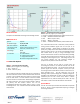
GG:Gearreduction
ratio(refertoload
curvesabove)
50,100,210
(lowerratiosarefasterbutpush
lessforce,andviceversa)
VV:Voltage 6,12
(DCvolts)
C:Controller SLimitSwitches
PPotentiometerFeedback
IIntegratedController
RRCServoIntegratedController
L12ControllerOptions
OptionS–EndofStrokeLimitSwitches
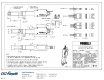
WIRING:(seelastpageforpinnumbering)
1‐Red–MotorV+
2–Black–MotorV‐(Gnd)
The–Sactuatorshavelimitswitchesthatwillturnoffpowerto
themotorwhentheactuatorreacheswithin0.5mmoftheend
ofstroke.Internaldiodes allow theactuatortoreverse away
from the limit switch.The limit switches cannot be moved
oncetheactuatorismanufactured.Whilevoltageisappliedto
themotor power pins, (1 & 2)the actuator extends.Reverse
the polarity and the actuator retracts. This can be
accomplished manually with a DPDT switch or relay, or using
anH‐Bridgecircuit.The–SmodelcannotbeusedwiththeLAC
controlboard.
OptionP–PotentiometerPositionFeedback
WIRING:(seelastpageforpinnumbering)
1‐Orange–FeedbackPotentiometernegativereferencerail
2‐Purple
–FeedbackPotentiometerwiper
3‐Red
–MotorV+(6Vor12V)
4‐Black–MotorV‐(Ground)
5‐Yellow–FeedbackPotentiometerpositivereferencerail
The–Pactuatorshavenobuiltincontroller,butdoprovidean
analog position feedback signal that can be input to an
external controller.While voltage is applied to the
motor
powerpins,(3&4)theactuatorextends.Reversethepolarity
andtheactuatorretracts.Thiscanbeaccomplishedmanually
with a DPDT switch or relay, or using an H‐Bridge circuit.
Positionoftheactuatorstrokecanbemonitoredbyproviding
anystablelowandhighreferencevoltageon
pins1&5,then
readingthepositionsignalonpin2.Thevoltageonpin2will
vary linearly between the two reference voltages in
proportiontothepositionoftheactuatorstroke.
The L12 –P actuator can be used as a linear servo by
connecting the actuatorto
an external controller such as the
LAC board offered by Firgelli.This control board reads the
position signal from the L12, compares it with your input
controlsignalthencommandstheactuatortomoveviaanon‐
board H‐bridge circuit.The LAC allowsany one of the
following control
inputs:Analog0‐5V or4‐20mA,or Digital 0‐
5VPWM,1‐2msStandardRC,orUSB.TheRCinputeffectively
transforms your L12 into a linear servo, which is a direct
replacement for any common hobby servo used in RC toys
androbotics.RefertotheLACdatasheetfor
moredetails.
SpecialNotes:
TheL12–Bcontroloptionhasbeendiscontinuedandreplaced
bythe‐S.The–Sisadirectreplacementrequiringnochanges
toexistinginstallations.
Rev C
Copyright 2016 Firgelli Technologies Inc.