Us er’s Manual 9640A Professional Enhanced Scan Tool
Scan Tool Information Complete the following list using the function “Tool Information” on page 3-4. Provide this information when contacting customer support. Serial No: SW ID: HW Ver: Boot Ver: Prod ID: Board ID: Burn Date: Burn Loc: Copyright Information Copyright © 2003 Actron Manufacturing, Inc. All rights reserved. The information, specifications and illustrations in this manual are based on the latest information available at the time of printing.
Safety ! Table of Contents ToC Section 1 –––––––––– Using this Manual 1 Section 2 –––––––––––– Getting Started 2 Section 3 –––––––– Using The Scan Tool 3 Section 4 ––– Global OBD II Diagnostics 4 Section 5 –––––––––––– GM Diagnostics 5 Section 6 ––––––––––– Ford Diagnostics 6 Section 7 ––––––––Chrysler Diagnostics 7 Section 8 ––––– Help & Troubleshooting 8 Appendix A ––––– Data Link Connectors A Appendix B –––––––––––––––– Glossary B
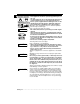
Safety Precautions For your safety, read this manual thoroughly before operating your Professional Enhanced Scan Tool. Always refer to and follow safety messages and test procedures provided by the manufacturer of the vehicle or equipment being tested. Your scan tool is intended for use by properly trained, skilled professional automotive technicians. The safety messages presented below and throughout this user’s manual are reminders to the operator to exercise extreme care when using this test instrument.
Safety Precautions ! Important Safety Instructions Risk of electric shock. • Do not exceed voltage limits between inputs as indicated in the “Specifications” on page 3-2. • Use extreme caution when working with circuits that have greater than 60 volts DC or 24 volts AC. Electric shock can cause injury. Risk of explosion. • Wear safety goggles and protective clothing, user and bystander. Everyday eyeglasses only have impact resistant lenses, they are NOT safety glasses.
Safety Precautions • Do not position head directly over or in front of throttle body. Do not pour gasoline down throttle body when cranking or running engine, when working with fuel delivery systems or any open fuel line. Engine backfire can occur when air cleaner is out of position. • Do not use fuel injector cleaning solvents when performing diagnostic testing. • Keep cigarettes, sparks, open flame and other sources of ignition away from vehicle.
Safety Precautions ! Risk of injury. • This equipment should be operated by qualified personnel only. • Use this equipment only as described in this manual. Use only the manufacturer’s recommended attachments. • Do not operate equipment with a damaged cord or if the equipment has been dropped or damaged, until it has been examined by a qualified service representative. Operation of this equipment by anyone other than qualified personnel may result in injury.
Safety Precautions Section 1 – Using This Manual Section 2 – Getting Started Vehicle Service Information . . . . . . . . . . . . . . . . . . . . . . . . . . . . . . . . . . . . 2-1 Introduction to On-Board Diagnostics . . . . . . . . . . . . . . . . . . . . . . . . . . . 2-1 Diagnostic Link Connectors (DLC) . . . . . . . . . . . . . . . . . . . . . . . . . . . . . . 2-3 OBD II (J1962) . . . . . . . . . . . . . . . . . . . . . . . . . . . . . . . . . . . . . . . . . . . . 2-3 Ford Historic . . . . . . . . .
Section 4 – Global OBD II Diagnostics ToC Manual Info . . . . . . . . . . . . . . . . . . . . . . . . . . . . . . . . . . . . . . . . . . . . . . . . . . 4-1 I/M Readiness . . . . . . . . . . . . . . . . . . . . . . . . . . . . . . . . . . . . . . . . . . . . . . . . 4-1 Read Codes . . . . . . . . . . . . . . . . . . . . . . . . . . . . . . . . . . . . . . . . . . . . . . . . . 4-2 Pending Codes . . . . . . . . . . . . . . . . . . . . . . . . . . . . . . . . . . . . . . . . . . . . . . . 4-3 Erase Codes .
Section 6 – Ford Diagnostics ToC Ford Historic Self-Test Routines . . . . . . . . . . . . . . . . . . . . . . . . . . . . . . . . 6-1 Manual Info . . . . . . . . . . . . . . . . . . . . . . . . . . . . . . . . . . . . . . . . . . . . . . . 6-1 Read KOEO Codes . . . . . . . . . . . . . . . . . . . . . . . . . . . . . . . . . . . . . . . . . 6-1 Read KOER Codes . . . . . . . . . . . . . . . . . . . . . . . . . . . . . . . . . . . . . . . . . 6-3 Review Codes . . . . . . . . . . . . . . . . . . . . . . . . .
Section 7 – Chrysler Diagnostics ToC Manual Info . . . . . . . . . . . . . . . . . . . . . . . . . . . . . . . . . . . . . . . . . . . . . . . . . . 7-1 Read Codes . . . . . . . . . . . . . . . . . . . . . . . . . . . . . . . . . . . . . . . . . . . . . . . . . 7-1 Read Temporary Codes . . . . . . . . . . . . . . . . . . . . . . . . . . . . . . . . . . . . . . . . 7-2 Erase Codes . . . . . . . . . . . . . . . . . . . . . . . . . . . . . . . . . . . . . . . . . . . . . . . . . 7-3 View Data . . . . . . . .
Section 1 – Using This Manual This manual contains instructions for use and setup of your scan tool. A table of contents and glossary are provided to make this manual easy to use. Some of the information shown in text or illustrations is obtained using optional equipment. A Sales Representative can determine option availability. This section contains a list of conventions used. 1 Safety Messages Refer to “Safety Precautions” on page i.
Using This Manual Questions and Responses Messages and user responses are CAPITALIZED. Example: The Scan Tool displays the Pending DTCs or a message stating SYSTEM PASS: NO FAULT DETECTED. Manual References 1 Used to reference other sections of the manual. References include the “Title” and page number (section-page). Example: For more information on DTCs, refer to “Diagnostic Link Connectors (DLC)” on page 2-3.
Section 2 – Getting Started The Professional Enhanced Scan Tool was developed by experts in the automotive service industry to help diagnose vehicles and assist in troubleshooting procedures. The tool monitors vehicle events and retrieves codes from the vehicle computer’s memory to pinpoint problem areas. All information, illustrations and specifications contained in this manual are based on the latest information available from industry sources at the time of publication.
Getting Started The original on-board diagnostics (OBD I) lacked consistency in communication and interface while allowing different interpretations amongst vehicle manufacturers. Ford and Chrysler used different types of engine control computers and data link connectors, and GM varied the trouble codes and communication protocols from year-to-year. The tables below highlight changes for GM, Ford, and Chrysler. If this seems confusing; don’t worry. Your tool makes it easy.
Getting Started OBD II stands for On-Board Diagnostics version II. OBD II is a system that the Society of Automotive Engineers (SAE) developed to standardize automotive electronic diagnosis. Technicians now can use the same tool to test any OBD II compliant vehicles without special adapters. The SAE established guidelines that provide: • a universal diagnostic test connector, called the data link connector (DLC), with dedicated pin assignments.
Getting Started the dashboard on the driver side of the vehicle. If the DLC is not located under the dashboard as stated, a decal describing its location should be attached to the dashboard in the area the DLC should have been located. Because the OBD II J1962 connector has power and ground, you only need a single cable connection to the tool for both power and tool communications. Attach the OBD II adapter cable to the extender cable, both supplied with the tool, to connect the tool.
Getting Started MECS MECS vehicles (1988 –1995) use either a 6-pin (with pigtail) or a 17-pin DLC. Use the MECS 6-pin adapter cable kit (P/N 9603) for both configurations. The MECS adapter cable kit includes jumper wires to connect to the MECS 17-pin DLC. The MECS adapter cable kit is not included with this tool. It is available through your dealer. Use the following diagrams to connect the adapter cable.
Getting Started MECS Ford Probe Certain Ford Probes have a WHITE TACH CONNECTOR IMPORTANT located very close to the 6-pin Self-Test connector and bundled in the same wiring harness. This is NOT the STI (Self Test Input) Pigtail. Connect the pigtail to the BLACK STI connector located farther back on the wire harness. If the tool is connected to the WHITE Tach connector, serious damage will result and may void warranty. Refer to the illustration.
Getting Started Chrysler Historic Prior to 1996, most Chrysler vehicles used either the SCI or LH DLC. Refer to “Appendix A - Data Link Connectors" for DLC type and location. The SCI adapter cable is included with the scan tool. The LH adapter cable (P/N 9605) can be purchased from your dealer. IMPORTANT Use the Battery Power cable to provide 12V to the tool when using the SCI adapter cable. SCI SCI The SCI (serial communications interface) DLC is a 6-pin connector located in the engine compartment.
Getting Started Within each general category, the DTCs are assigned to specific ranges that cover certain vehicle systems.
Section 3 – Using The Scan Tool THE SCAN TOOL B C D E F G H I J a b Serial Port (DB9 Male Connector) – provides a serial RS232 connection for a printer and for updating the software. DLC Port (DB15 Male Connector) – provides connection for vehicle interface. 12V Power Jack LCD Display – backlit, 4 line x 20 character with contrast adjustment. BACK key – goes to the previous screen or level. UP/DOWN arrows – scrolls UP or DOWN and moves the selection pointer (`).
Using The Scan Tool Specifications Display: Backlit LCD, 4 line, 20 column, contrast adjust Operating Temperature: 0 to 50°C (32 to 122°F) Storage Temperature: -20 to 70°C (-4 to 158°F) Internal Power: 6-AAA cells External Power: 6.5 to 15.5 Volts ✓ Most vehicle control modules require at least 8.0 V to operate properly. Power Dissipation: 3.5 Watts maximum Width Dimensions: Height 1.625" 41 mm Weight: 3.16 lbs (1432 g) 5.25" 133 mm Length 9.
Using The Scan Tool Power ✓ Refer to “Scan Tool Does Not Power Up” on page 8-1 if you encounter problems. Internal Batteries When the scan tool is not connected to the vehicle, the ON/OFF key turns ON the scan tool. Press and hold down the ON/OFF key for at least one second to turn ON the scan tool. To conserve battery power, the scan tool disables the display’s back-lighting and turns OFF after a period of inactivity. Each time the scan tool is powered up, the voltage of the batteries is checked.
Using The Scan Tool Scan Tool Setup Tool Setup allows you to change the measurement units and LCD contrast, turn beeper On/Off and display tool information. The settings remain until the internal batteries become discharged. Main Menu ` Vehicle Diagnosis Tool Setup Tool Self-Tests | [ ~ Setup Tool ` 1)English/Metric 2)Display Contrast 3)Beeper [ ~ Measurement Units To change the measurement units, use the UP/DOWN arrow keys to select English/Metric and press ENTER .
Using The Scan Tool ❒ ❒ ❒ ❒ Seiko DPU-414 Kodak DICONIX 180si (serial printer model) Lexmark Model 2480 with optional serial interface (p/n 12T0154) Panasonic KX-P1131 printer Cabling ❒ Type: A standard RS-232 type cable. ❒ Scan Tool end: DB9F (female) connector. ❒ Printer end: • Use a DB9M (male) connec-tor for the Seiko and DB9 Kodak printers. • Use a DB25 male connector for the Lexmark and Panasonic printers.
Using The Scan Tool Press ENTER after selecting each setting. Follow the instructions displayed on the screens. For the printer to work properly, the tool and the printer must be set to the same configuration. Change the settings accordingly. To change the settings, press the LEFT arrow and then ENTER . Use the BACK key to return to the previous menu. The new printer settings are tested by printing the ASCII character set. Press to continue.
Using The Scan Tool CONNECTING THE SCAN TOOL To diagnose a vehicle, connect the DLC and power adapter (if applicable) to the scan tool. Refer to “Diagnostic Link Connectors (DLC)” on page 2-3 of Getting Started. Diagnostic Connector If you just want to power up the tool to do its self-tests, code lookup, review or printing data from the last vehicle tested, then you do not need to attach the cable to the Data Link Connector. The internal battery provides power for this.
Using The Scan Tool Changing the Vehicle Changing vehicles erases all data stored in the tool. The default is YES. Press ENTER to continue. Picking New Vehicle Erases All Stored Data. Continue? NO Four Vehicle Options are available: General Motors, Ford, Chrysler and Global OBD II. Global OBD II does not require additional information and takes you directly to the function list. The other three require additional information so that the tool can communicate with the vehicle.
Using The Scan Tool User Interface The scan tool is designed to be as intuitive as possible. All menu and lists operate the same way. Use the UP/DOWN arrow keys to move UP/DOWN through the display or move the cursor (`) to a selectable item. Press the ENTER key to select the function or item. To return to previous screens, press the BACK key. This information can be viewed on the scan tool by pressing the HELP key after powering up the scan tool.
Using The Scan Tool Custom Data List The Custom Data List allows you to select certain PIDs from the Entire Data List, such as those PIDs that pertain to a specific driveability symptom or system. The scan tool asks if you want to view the instructions. Once in the Custom Data List menu, follow the instructions described below. A « symbol will be displayed next to all selected PIDs. Use the UP/DOWN arrow keys to scroll through the list.
Section 4 – Global OBD II Diagnostics The first time the scan tool communicates with the vehicle, the communication type is automatically detected, and is used until the scan tool is turned OFF or another vehicle is diagnosed. ✓ ✓ If an Error Message displays, make sure the OBD II connector is securely attached, and the ignition key is ON. Cycle the ignition key to OFF for 10 seconds, then ON. This may be required to reset the computer. If required, select YES to try again.
Global OBD II Diagnostics Select I/M Readiness from the OBDII Function List menu and press ENTER . The scan tool displays a message stating whether the I/M Readiness monitors are completed. On-Board Readiness | Tests Are Complete Use [ To View Test~ OBDII Function List | ` 1)I/M Readiness 2)Read Codes [ 3)Pending Codes ~ Not All Supported On-Board Readiness Tests Are Complete. Use [ To View ~ Use the DOWN arrow key to view the monitor statuses.
Global OBD II Diagnostics Write down the DTCs for reference and then press BACK to return to the OBD II Function List. P0107 Mod$10 1/1 MAP/BARO Circuit Low Input [ ~ PENDING CODES Pending Codes are also referred as “continuous monitor” and “maturing codes”. An intermittent fault causes the computer to store a code in memory. If the fault does not occur within 40 warm-up cycles, the code clears from memory.
Global OBD II Diagnostics Select Erase Codes and press the ENTER key. A message appears asking if you are sure. Press the LEFT/RIGHT arrow keys to move the brackets to the desired response and press ENTER . OBDII Function List ` 4)Erase Codes 5)View Data 6)View Freeze Data | ] [ ~ Erase Diagnostic Results and Codes? Are You Sure? Yes ~ Selecting NO displays a COMMAND CANCELLED message prompting you to press ENTER to continue back to the OBDII Function List.
Global OBD II Diagnostics After making a selection, press ENTER to establish a communication link. Multiple PIDs may be sent if the vehicle is equipped with more than one computer module — Powertrain Control Module (PCM), Transmission Control Module (TCM), etc. The scan tool identifies them by their identification names (ID) assigned by the manufacturer (i.e. $40 or $1F).
Global OBD II Diagnostics O2 MONITOR TEST ✓ The O2 Monitor Test is NOT AN ON-DEMAND TEST. O2 sensors are NOT tested when selected via the menu. The O2 sensors are tested when engine operating conditions are within specified limits. OBD II regulations require that applicable vehicles monitor and test the oxygen (O2) sensors to determine problems related to fuel and emissions. The O2 Monitor Test allows retrieval of completed O2 sensors monitor test results.
Global OBD II Diagnostics NON-CONTINUOUS TESTS The Non-Contin (Non-Continuous) Tests obtains test results for emission-related powertrain components and systems that are not continuously monitored. The Non-Contin Test function is useful after servicing or after erasing the vehicle’s memory. Test results do not necessarily indicate a faulty component or system. The scan tool asks the vehicle for any available non-continuous test IDs, and then displays them in a list.
Global OBD II Diagnostics Select On-Board Systems from the OBDII Function List and press ENTER. A list of on-board systems and components available for testing display on the screen. OBDII Function List | ` 10)Record Data ] 11)Vehicle Info [ 12)Modules Present ~ Select a test and press ENTER to activate the test. The manufacturer is responsible for determining the criteria to automatically stop the test. Refer to the appropriate vehicle service manual.
Global OBD II Diagnostics On the next screen, select a triggering method. Manual Trigger allows the technician to use the ENTER key. Trigger On Codes automatically triggers when a DTC is indicated by the vehicle. Pick Trigger Method `1)Manual Trigger 2)Trigger On Codes Once the trigger method is selected, the scan tool will begin recording data. When the trigger event (either a DTC or a Press of the ENTER key) occurs, the time is recorded and data from the last five frames is saved.
Global OBD II Diagnostics Calibration Verification Numbers (CVNs) are calculated values required by OBD II regulations. CVNs are reported to determine if emission-related calibrations have been altered. Multiple CVNs may be reported for a control module. ✓ The calculation may take several minutes the first time the CVNs are requested. Select Vehicle Info from the OBDII Function List and press ENTER.
Global OBD II Diagnostics Most of the functions displayed on the Review Data screen are self explanatory. Only one function, Playback, needs detailed instructions. Follow the prompts and instructions provided by the scan tool. No Data Stored In Tool. Use VEHICLE INFO Before Reviewing. ~ If data does not exist for the function you selected to review (for example Vehicle Info), a message informs you to run the function first. Playback The Playback function is used to play back a recording.
Global OBD II Diagnostics PRINT DATA This function allows you to print the diagnostic information stored in the Scan Tool. The scan tool’s internal battery power can be used to print data. Select Print Data and press the ENTER key. The scan tool informs you of the printer settings (Custom or Default), then asks if you wish to change them. OBDII Function List 13)Review Data ` 14)Print Data 15)Code Lookup | ] [ ~ Tool Set To Default| Printer Settings.
Global OBD II Diagnostics Printing Playback Data When printing playback data, the Start Frame and End Frame need to be defined. After selecting Playback and pressing ENTER , the Start Frame screen shows the earliest possible frame. Use the UP/DOWN arrow keys to change the frame number and then press ENTER . Start Frame: -5 Use Scroll Wheel To Change Frame Number Press ENTER to Cont. ~ Next, the End Frame screen displays the latest possible frame.
Global OBD II Diagnostics CODE LOOKUP Code Lookup is used to look up definitions of Diagnostic Trouble Codes (DTCs) stored in the Scan Tool. The scan tool does not require power from the vehicle to perform this function. Internal battery power can be used. To look up DTC definitions, select Code Lookup from the OBDII Function List. OBDII Function List 13)Review Data 14)Print Data 15)Code Lookup | ] [ ~ When entering codes, all characters must be entered. Only one character can be changed at a time.
Section 5 – GM Diagnostics ✓ If the Scan Tool displays an Error Message, make sure the cables and adapters are securely attached and the ignition key is ON. Cycle the ignition key to OFF for 10 seconds, then ON. Attempt the test selected again. If the problem remains, refer to “Error Messages” on page 8-2. GM HISTORIC (OBD I) DIAGNOSTICS ✓ Some 1994 and 1995 vehicles use the 16-pin OBD II connector, but are not OBD II compliant. They still use the OBD I application software.
GM Historic (OBD I) Diagnostics One of two screens displays: If the diagnostic checks are working correctly and no DTCs have been stored in vehicle’s memory, a SYSTEM PASS message displays. If not, the tool displays a screen indicating the number DTCs. System Pass: No Faults Detected. ~ Use the UP/DOWN arrow keys to scroll through the codes. Note the codes and press FUNC to return to the GM Function List.
GM Historic (OBD I) Diagnostics A message confirming that the Erase Codes command was successful displays. Press ENTER to return to theGM Function List. Erase Codes Command Sent. Perform READ CODES Function To Verify Erase. Manual Erase Methods Alternate Method 1: 1) Turn Ignition Key Off. 2) Locate Fuse Box and Remove ECM Fuse. 3) Wait 20 seconds. 4) Replace the Fuse. Alternate Method 2: 1) Turn Ignition Key Off. 2) Remove Power from Scan Tool. 3) Disconnect Scan Tool from Vehicle.
GM Historic (OBD I) Diagnostics Select Data To View| 1)Entire Data List ` 2)Custom Data List After making a selection, press ENTER ~ to establish a communication link. Select the type of data to view. Refer to “Viewing Data” on page 3-9 for Entire or Custom Data Lists. Use the UP/DOWN arrow keys to scroll through the PIDs. A Vehicle Data List header marks the beginning. Custom Data List Codes Present Yes 1ST GEAR SW ON [ A/F RATIO 18.
GM Historic (OBD I) Diagnostics Select a method and press ENTER. The tool will establish a communication link with the PCM. If Manual Trigger is selected, press ENTER to begin recording. Trigger On Codes will not show this screen. The function runs automatically and stops when the tool’s memory is filled. **Ready To Record** Press ENTER Anytime To Start Recording. ~ **Recording Data** Stops Automatically When Memory is Full.
GM Historic (OBD I) Diagnostics Select Playback from the Review Data screen and press ENTER : ✓ Review Data 1)DTC (Codes) ` 2)Playback | ~ If a recording does not exist in the tool memory, then the tool will display a “NO RECORDING PRESENT” message. Perform “Record Data” on page 5-4. Select which list to playback. Refer to “Viewing Data” on page 3-9 of Using The Scan Tool for Entire or Custom Data Lists.
GM Historic (OBD I) Diagnostics Field Service Mode can be operated with the ignition Key On-Engine Off (KOEO) or with the Key On-Engine Running (KOER). ✓ ✓ Vehicles equipped with climate control computers do not use Field Service Mode. Some 1994 & 1995 vehicles equipped with a 12-pin ALDL connector with pins A and B shorted will not cause the CHECK ENGINE light to flash codes. Select Field Service from the GM Function List and press ENTER.
GM Historic (OBD I) Diagnostics — DTC 12 (No RPM reference pulse) should display first since the engine is not running. If not, problems exist in the PCM or Check Engine light circuitry. Code 12 will look like: FLASH-pause-FLASH-FLASH — long pause. Code 23 will look like: FLASH-FLASH-pause-FLASH-FLASH-FLASH — long pause. 4) When Field Service Mode is ON, most computer controlled Relays and Solenoids will be turned ON, except for the fuel pump relay and fuel injectors.
GM Enhanced (OBD II) Diagnostics GM ENHANCED (OBD II) DIAGNOSTICS IMPORTANT ✓ ✓ ✓ This system applies to GM vehicles manufactured from 1996 to present. Some GM vehicles in 1994 and 1995 were equipped with this system. Refer to “Appendix A - Data Link Connectors". GM vehicles manufactured from 2000 to present automatically use Global OBD II Diagnostics. If an Error Message displays, make sure the OBD II connector is securely attached, and the ignition key is ON.
GM Enhanced (OBD II) Diagnostics • Since IGN (ignition): PASS, FAIL, P/F, or NOT RUN Provides the DTC status during this power-up. P/F (Pass/Fail) indicates the PCM detected the DTC that passed and failed at least once during this power-up cycle. NOT RUN means the PCM has not tested for the condition that set the DTC during this power-up cycle. • Since Clear: PASS, FAIL, P/F, or NOT RUN Provides the DTC status since the last time the codes were erased.
GM Enhanced (OBD II) Diagnostics Select View Data from theGM Function List and press ENTER . GM Function List | 4)Erase Codes ] ` 5)View Data [ 6)View Freeze Data ~ GM arranges the PIDs in four groups: Select Pid Group ` Analog O2 Misfire ❒ Analog: viewing of analog sensor ❒ ❒ ❒ ✓ | [ ~ signals, such as measured voltage from O2 sensors, temperature sensors, and air flow sensors. O2: viewing oxygen sensor information. Misfire: viewing of cylinder misfire information.
GM Enhanced (OBD II) Diagnostics If one or more control modules stops responding, the tool will display a message that it is not responding. If you choose to continue, dashes will replace the module ID. Module $1F is not Responding. Continue Without it? Yes ~ Press FUNC to return to the GM Function List. View Freeze Data When an emission-related fault occurs, certain vehicle conditions are recorded by the on-board computer. This information is referred to as a Freeze Frame data.
GM Enhanced (OBD II) Diagnostics Record Data Refer to “Record Data” on page 4-8 of Global OBD II Diagnostics. GM groups the PIDs into four categories: ❒ Analog: viewing of analog sensor signals, such as measured voltage from O2 sensors, temperature sensors, and air flow sensors. ❒ O2: viewing oxygen sensor information. ❒ Misfire: viewing of cylinder misfire information. ❒ Digital: viewing of switches, solenoids and relays. ✓ Some GM trucks manufactured in 1996 – 1998 have only one PID group.
GM Enhanced (OBD II) Diagnostics 5 5 – 14 • • • • • • • • • • • • • • • • • • • • • • • • • • • • • • • • • • • • • • • • • • • • • • • • • • • • • • •
Section 6 – Ford Diagnostics FORD HISTORIC SELF-TEST ROUTINES Due to different processor calibrations, the Ford Function List for a particular vehicle may or may not appear as shown. Based on the vehicle information entered at the Vehicle Setup menu, the tool automatically recognizes the computer system installed. If the function is not supported by the vehicle, than the scan tool does not display it. ✓ ✓ ✓ Ford vehicles manufactured from 2000 to present automatically use Global OBD II Diagnostics.
Ford Historic Self-Test Routines Select Fast Codes or Slow Codes and press ENTER. Follow the instructions step-by-step. 1) Set Parking Brake. 2) Put Transmission In Park Or Neutral. 3) Turn A/C Off. 4) Start Engine — Let Idle Until Hot. 5) Turn Ign Key Off. 6) Wait 10 Seconds. Turn Key On-Engine Off. Do Not Start Engine. Avoid Cooling Fan! It May Turn On During Test.
Ford Historic Self-Test Routines After viewing and noting the KOEO codes, use the DOWN arrow key to view Continuous Memory codes. When done, press FUNC to return to the Ford Function List. Memory Code 126 MAP Sensor Signal ] Voltage Higher or [ Lower Than Expected~ Read KOER Codes The Read KOER Codes function activates the KOER (Key-On-Engine-Running) self-test which retrieves KOER DTCs that are present when the engine is running.
Ford Historic Self-Test Routines ❒ If Applicable, set Octane Switch To Premium. The tool will prompt the user to: ❒ Work Steering Wheel ❒ Pump Brake Pedal & Cycle OD (overdrive) Cancel Switch. ✓ Observe Screen for Prompt to Perform the next action. ❒ Quickly Press And Release Throttle. One Time Only! 6 After performing these steps, wait for the tool to retrieve DTCs. When the test is done, turn Ign Key OFF and press ENTER. Test Completed Turn Ign Key Off.
Ford Historic Self-Test Routines 1) Set Parking Brake. 2) Transmission In Park Or Neutral. 3) Turn A/C Off. 4) Start Engine — Let Idle Until Hot. 5) Turn Ign Key Off. 6) Wait 10 Seconds. Start Engine — Let Idle. 7) If Vehicle Has A Manual Transmission, Release Clutch. If a KOER code of 98 or 998 is detected, then the fault must be fixed before performing this function. Press the BACK key to return to the Ford Function List. Can't Run Timing Check. Code 98/998 Detected.
Ford Historic Self-Test Routines Erase Codes The vehicle service manual may recommend erasing Continuous Memory Codes from vehicle’s memory, and then drive vehicle to duplicate the malfunction before beginning a diagnostic test. If KOEO codes were read using Fast Codes, the memory codes have already been erased. Only Continuous Memory Codes can be erased from the vehicle without repairing the fault. To remove KOEO and KOER Codes, the fault must be repaired since they only exist when a fault exists.
Ford Historic Self-Test Routines Only Memory Codes Are Erasable! Press ENTER to Cont~ ! CAUTION To Erase KOEO And KOER Codes, You Must Fix Cause of Code. Press ENTER to Cont~ Never Lay Tools On Vehicle Battery. Tools May Create Shorts And Cause Harm To User And Damage To Tools, Battery And Electrical System. Follow all instructions on the display. 1) Turn Ign Key Off. 2) Remove Negative (–) Battery Cable. 3) Hold Down Break Pedal for 10 Seconds. 4) Reattach Negative (–) Battery Cable.
Ford Historic Self-Test Routines Instructions are available for viewing. The default is YES. If NO is selected, the test will begin to initialize. View Instructions For Wiggle Test? NO ~ If YES is selected, the following instructions will appear. ❒ Gently tap and shake the sensor. ❒ Wiggle the sensor connectors. ❒ Twist and shake the wiring between the sensor and the PCM. Press ENTER to continue. The next instruction states: Beeper sounds and message displayed while fault exists.
Ford Historic Self-Test Routines 5) Turn Ign Key Off. 6) Wait 10 Seconds. Turn Key On-Engine Off. Do not Start Engine. ! CAUTION Avoid Cooling Fan! It May Turn On During Test. The test screen indicates the time remaining. Do not touch vehicle or tool keys during this time until the next screen appears. Procedure Runs Less Than 3 Minutes. Depress the accelerator pedal fully to turn ON relays and solenoids. Do the same to turn them OFF. This can be repeated as many times as required to locate the fault.
Ford Historic Self-Test Routines After pressing ENTER to continue, the scan tool prompts the PCM for the Cylinder ID. The PCM has 15 seconds to respond. If no ID was received, the tool prompts the user to try again. Once the ID is received, a Read KOER Self-Test begin. Follow all user prompts: ❒ Work Steering Wheel ❒ Pump Brake Pedal & Cycle OD (overdrive) Cancel Switch. ✓ Observe Screen for Prompt to Perform the next action. ❒ Quickly Press And Release Throttle.
Ford Historic Self-Test Routines Turn the ignition key Off and press ENTER to continue — the tool prompts the user to retest (up to three times). If required, rerun the test to double check the results, or to check for weaker or dead cylinders. FUNC to return to the Ford Function List. IVSC-Speed Ctrl (EEC-IV Vehicles) When done, press The IVSC-Speed Ctrl (Integrated Vehicle Speed Control) is Ford’s computerized cruise control system on EEC-IV vehicles.
Ford Historic Self-Test Routines Use the UP/DOWN arrow keys to scroll through the KOEO Code listing. Be sure to write down any codes for reference. IVSC KOEO Code 568 SCVAC Failure: Speed Control Vacuum Circuit Failure ~ Reading IVSC KOER Codes Select Read KOER Codes from the sub-menu and press ENTER. To retrieve codes, follow the instructions on the tool screen as follows: 1) Set Parking Brake. 2) Put Transmission In Park Or Neutral. 3) Turn A/C Off. 4) Start Engine — Let Idle Until Hot.
Ford Historic Self-Test Routines Select STAR Test Mode from the Ford Function List and press ENTER Ford Function List ` 9)STAR Test Mode 10)Code Lookup 11)Print Data Follow the instructions on the tool screen to access DTCs from the PCM. Pressing ENTER begins test. STAR Mode. STO: Test/Hold On: Hold ENTER To Test. The TEST/HOLD parameter indicates the state the STI (Self-Test Input). The ENTER key toggles this state from TEST to HOLD. STAR Mode STO:LOW Test/Hold On: Test ENTER To Hold.
Ford Historic Self-Test Routines Code Lookup Code Lookup is used to look up definitions of Diagnostic Trouble Codes (DTCs) stored in the scan tool. The scan tool does not require power from the vehicle to perform this function. Internal battery power can be used. Select Code Lookup from the Ford Function List . Ford Function List 11)Print Data ` 12)Code Lookup 13)Manual Info Only one character can be changed at a time.
Ford Historic Self-Test Routines DCL Data Functions (EEC-IV Vehicles) DCL (Data Communication Link) Data functions are used to view and record engine data transmitted from the vehicle on EEC-IV vehicles beginning in 1990. These functions allow viewing of data parameters in real time to pinpoint problems when they occur. The tool also has the ability to record these data parameters as the vehicle is operated to locate intermittent problems.
Ford Historic Self-Test Routines Select Record Data from the DCL Function List and press ENTER. If a recording currently exists in memory, a message to ERASE OLD RECORDING displays. DCL Function List 1)View Data ` 2)Record Data 3)Playback Data ~ Cannot Record. Old Recording Filled Up Memory. Erase Old? Yes ~ The tool maintains only one recording at a time, so be sure to thoroughly review an old recording before erasing it.
Ford Historic Self-Test Routines If data is recorded, the tool will prompt the user to playback data as an Entire Data List or a Custom Data List. Refer to “Viewing Data” on page 3-9 of Using The Scan Tool for help on Data Lists. Playback Data As: ` 1)Entire Data List 2)Custom Data List ~ After selecting the data List type, press the ENTER key to start playing back the recorded data. BOO-Brake Sw Canst Purge ECT Sensor(v) Frame:16 Time: ON | ON ] 3.3 [ 24.
Ford Enhanced (OBD II) Diagnostics FORD ENHANCED (OBD II) DIAGNOSTICS IMPORTANT This system applies to Ford vehicles manufactured from 1996 to present. Some vehicles in 1994 and 1995 were equipped with the EEC-V system. Refer to “Appendix A - Data Link Connectors". Ford vehicles manufactured from 2000 to present automatically use Global OBD II Diagnostics.
Ford Enhanced (OBD II) Diagnostics Read All DTC The Read All DTC function retrieves all DTCs (MIL, non-MIL, Pending and Memory) stored in the vehicle’s computer module(s). This function can be performed with the KOEO or KOER. Select Read All DTC and press ENTER . The Scan Tool retrieves the DTCs stored in the vehicle’s computer module(s).
Ford Enhanced (OBD II) Diagnostics Ford arranges the PIDs in six groups: ❒ Standard Info: viewing of analog ❒ ❒ ❒ ❒ ❒ 6 Data Group ` Standard Info O2 Sensor Info Misfire Info | [ ~ sensor signals, such as measured voltage from O2 sensors, temperature sensors, and air flow sensors. O2 Sensor Info: viewing oxygen sensor information. Misfire Info: viewing of cylinder misfire information. Auto Trans Info: viewing of automatic transmission information.
Ford Enhanced (OBD II) Diagnostics Quick Tests The Quick Tests checks the integrity and performance of the EEC-V and PTEC system. It is performed first in most diagnostic procedures and after servicing to verify the repair. Three Quick Tests are performed on all Ford vehicles. ❒ KOEO On Demand: Key On-Engine Off (KOEO) Self-Test. ❒ KOER On Demand: Key On-Engine Running (KOER) Self-Test. ❒ KOEO Output State. Additional Quick Tests for OBD II 7.3L Powerstroke Diesel vehicles.
Ford Enhanced (OBD II) Diagnostics The following system components are tested: ❒ ❒ ❒ ❒ Electric radiator cooling fan - Avoid cooling fan! Fuel pump Check engine light Idle speed control solenoid If no Codes are read, the System Pass System screen displays. Pass: No DTCs Found ~ If problems exist, the screen indicates that codes have been read. Use UP/DOWN arrow keys to view them. Press the FUNC key to return to the Ford Function List. DTCs Found: 2 Use [ To View DTCs Write Down Codes For Reference.
Ford Enhanced (OBD II) Diagnostics After pressing ENTER to continue, the KOER self-tests begins. The tool prompts you to: Test In Progress Approximate Time Left 4:00 Press BACK to Quit ~ ❒ Work Steering Wheel ❒ Pump Brake Pedal ❒ Cycle OD (overdrive) Cancel Switch (on some Automatic Transmissions. When the test is done, the DTCs found display on the screen. Use UP/DOWN arrow keys to view Codes. If no codes are read, the System Pass screen is displayed.
Ford Enhanced (OBD II) Diagnostics Quick Tests (7.3L Powerstroke Diesel Only) These additional Quick Tests are available when testing a truck equipped with a 7.3L Powerstroke Diesel engine. KOEO Inj. Buzz The KOEO Inj. Buzz is a functional test performed on demand with the ignition key ON and Engine OFF. The test determines if the injector circuits and solenoids are operating electrically correct and without faults.
Ford Enhanced (OBD II) Diagnostics When the vehicle has finished the test, the DTCs found display on the screen. If no codes are read, the System Pass screen is displayed. Use UP/DOWN arrow keys to view Codes. DTCs Found: 2 Use [ To View DTCs Write Down Codes For Reference. ~ Press the FUNC key to return to the Ford Function List or BACK to return to the Quick Tests screen. KOER Cyl. Cont. The KOER Cyl. Cont.
Ford Enhanced (OBD II) Diagnostics Select KOER Switch from the Quick Tests screen. Press ENTER to begin the test. Quick Tests KOER Glow Plug KOER Cyl. Cont. ` KOER Switch | ] ~ Exhaust gases are harmful or FATAL. Always operate vehicle in a well-ventilated area. The KOER switch test is done with the engine running. Do not over-rev engine. Observe all safety precautions. Follow all user interaction required to run the KOER Switch Self-Test. The tool will display a prompt when action is required.
Ford Enhanced (OBD II) Diagnostics Record Data Refer to “Record Data” on page 4-8 of Global OBD II Diagnostics. Ford groups the PIDs into six categories: • Standard Info: viewing of analog sensor signals, such as measured voltage from O2 sensors, temperature sensors, and air flow sensors. • O2 Sensor Info: viewing oxygen sensor information. • Misfire Info: viewing of cylinder misfire information. • Auto Trans Info: viewing of automatic transmission information.
Ford Enhanced (OBD II) Diagnostics 6 6 – 28 • • • • • • • • • • • • • • • • • • • • • • • • • • • • • • • • • • • • • • • • • • • • • • • • • • • • • • • •
Section 7 – Chrysler Diagnostics ✓ ✓ ✓ Due to different processor calibrations used, the function list for a particular vehicle may or may not appear as shown. Based on the vehicle information entered at the Vehicle Setup menu, the tool recognizes the computer system installed. If an Error Message displays, make sure the adapter cable is securely attached, and the ignition key is ON. Cycle the ignition key to OFF for 10 seconds, then ON. This may be required to reset the computer.
Chrysler Diagnostics Use the UP/DOWN arrow keys to scroll through the codes. Write down the codes for reference or print them later. ENG: 31/P0443 EVAP Purge Solenoid Circuit ~ The DTCs are categorized by ENG (engine) or TRANS (transmission). The Chrysler MIL code (3-digit) and SAE code (5-digit) follow on the first line. ENG: 31/P0443 EVAP Purge Solenoid Circuit TRANS: 18/P1792 Battery ] Disconnected [ (In Last 50 Cycles) ~ ~ There may be times where only one or both display.
Chrysler Diagnostics Use the UP/DOWN arrow keys to scroll through the codes. Note the codes and press FUNC to return to the Chrysler Functions list. ENG: 14/P0107 MAP Voltage Too Low Use the UP/DOWN arrow keys to scroll through the codes. Write down the codes for reference or print them later. ENG: 31/P0443 EVAP Purge Solenoid Circuit ~ ~ The DTCs are categorized by ENG (engine) or TRANS (transmission). The Chrysler MIL code (3-digit) and SAE code (5-digit) follow on the first line.
Chrysler Diagnostics A message confirms the codes are erased. Press ENTER to return to the Chrysler Functions menu. Codes Erased. VIEW DATA The View Data function allows the mechanic to view the vehicle’s parameter identification data (PIDs) in real time. As the PCM monitors the PIDs, they are sent to the scan tool. Apart from Read Codes, View Data is the most useful diagnostic function for isolating the cause of a vehicle operation problem.
Chrysler Diagnostics RECORD DATA The Record Data function records vehicle PID (Parameter Identification) data while the vehicle is parked or being driven. This function is mainly used for diagnosing intermittent driveability problems that cannot be isolated by any other method. The tool records data based on time (5 frames prior to the start of the recording, and for a duration after). The time after depends on the vehicle data rate.
Chrysler Diagnostics If Manual Trigger is selected, the scan tool initializes by recording the first five frames. When done, press ENTER. **Ready To Record** Press ENTER Anytime To Start Recording. Stops Automatically ~ Press the BACK key twice to return to the Chrysler Functions menu. Waiting For Trouble Code To Trigger The Start of Recording BACK To Exit ~ The scan tool recording time varies. A recording consists of 5 frames of data prior to the trigger and several frames after the trigger.
Chrysler Diagnostics To test a switch, press the switch and check the tool display. If the switch is available for testing, the tool displays the current status of the switch. Testing Switch: A/C CLUTCH REL SWITCH IS HIGH To finish testing switch, press the switch again. The switch status on the bottom should change if the switch is working. ~ To test another switch, press the BACK key to return to the Select SW to Test screen. To return to the Chrysler Functions list, press the FUNC key.
Chrysler Diagnostics To return to the Chrysler Functions list, press the FUNC key. IDLE SPEED TEST The Idle Speed Test is used to test the functionality of the vehicle idle speed control system. The test allows the user to enter the desired engine speed. The test vehicle should respond by matching the speed commanded. If the vehicle matches the demanded engine speed, the idle speed control system is functioning properly. Select Idle Speed Test from the Chrysler Functions list and press ENTER .
Chrysler Diagnostics One sensor will be displayed per screen. Use the UP/DOWN arrow keys to scroll through the supported sensors. The tool displays the status of the sensor. Viewing Sensor: ADPT FUEL(%) 5.00[ ~ Press the BACK or FUNC key to end the test and return to the Chrysler Functions list.
Chrysler Diagnostics Select Reset EMR Lamp from the Chrysler Functions list and press ENTER . Turn ignition key On, but do not start engine. Press ENTER to reset the EMR lamp. Chrysler Functions 9)Sensor Test 10)Controller Info ` 11)Reset EMR Lamp | ] [ ~ EMR Lamp Is Reset. ~ Press the FUNC or BACK key to return to the Chrysler Functions list. SET BASIC TIME The Set Basic Time function is used when checking basic timing. This feature suspends spark scatter at idle.
Chrysler Diagnostics When returning to the Chrysler Functions list, timing will remain fixed. This allows the mechanic to use the Sensor Test function and read sensor data. To restore timing, the Abolish Request mode must be selected from the Select Request Mode menu. Depending on the Request Mode sent to the PCM, the tool will display the following messages: • Basic Timing Has Been Abolished. • Basic Timing Has Been Initiated. Spark Is Being Fired At Predetermined Set Point Without Spark Scatter.
Chrysler Diagnostics Use the UP/DOWN arrow keys to view the recorded PID data of each frame. The end of the list is reached when only the ] (up) icon is visible. Use the LEFT/RIGHT arrow keys to scroll back and forth through the frames. The RIGHT arrow key advances to the next frame, “wrapping around” to the earliest frame when the final frame is reached. The LEFT arrow key goes back to the previous frame, again “wrapping around” to the final frame.
Chrysler Diagnostics Press ENTER to display the definition. Both the MIL code and SAE code display with the definition when applicable. Eng: 46/P0401 EGR System Performance The Chrysler MIL code (3-digit) and SAE code (5-digit) appear on the first line. There may be times where only one or both code types display. Dashes display if the DTC type does not exist. Certain MIL codes may have more than one definition for the same vehicle. The down arrow icon indicates more definitions are available.
Chrysler Diagnostics 7 7 – 14 • • • • • • • • • • • • • • • • • • • • • • • • • • • • • • • • • • • • • • • • • • • • • • • • • • • • • • •
Section 8 – Help & Troubleshooting HOW TO USE ON-LINE HELP Operating Error. | Check Connections! Try Again? No The software contains On-Line Help for specific tool screens, functions, and error messages. When the icon (|) appears in the upper right-hand corner of the display, On-Line Help is available. To enter On-Line Help, press the HELP key. For the screen above, the help message would look like this The text in On-Line Help screens are in CAPITAL LETTERS.
Help & Troubleshooting PIN 4 (GND) PIN 2 (BAT+) PIN 6 (GND) PIN 16 (BAT+) LH DLC J1962 (OBD II) DLC Scan Tool does not power up. Is battery fully charged? Measure Voltage between BAT + and GND pins. NO Charge battery. YES Measure resistance between GND pin and frame ground. Above 8V? NO NO less than 5 ohms? YES Contact Customer Service Center. Repair Ground circuit. Refer to a service manual. YES Open exists in power circuit. Check for a blown fuse or an open wire.
Help & Troubleshooting Check the following if an error message displays: ❒ Verify ignition key is ON — not in the ACCESSORIES position. ❒ Make sure the Scan Tool cable is securely connected to the vehicle’s DLC. ❒ Examine the DLC closely and check for ❒ ❒ ❒ ❒ ❒ ❒ cracked or recessed pins, or for any substance that could prevent a good electrical connection. Verify that the vehicle you are testing is an OBD II-compliant vehicle.
Help & Troubleshooting TOOL SELF-TESTS If you experience problems when performing the Tool Self-Tests, contact technical support at 1-800-228-7667 (8:00 – 6:00 EST Monday – Friday) or send an email to tech_support@actron.com Tool Self-Tests check the display, keypad, internal memory, and RS-232 interface. After powering up the Scan Tool, the Main Menu displays four choices. Select Tool Self-Test with the UP/DOWN arrow keys and press ENTER .
Help & Troubleshooting Memory Test If the Scan Tool has trouble playing back recorded data, displaying trouble code definitions, or doing any other function that uses internal memory, then it is a good idea to run the Memory Test. From the Tool Self-Test menu, select Memory Test and press ENTER. A MEMORY TEST message displays and the screen fills with dots as the internal memory is tested. ✓ Memory Test . . . . . . .......... The Memory Test may take several minutes to complete.
Help & Troubleshooting ---[Print Test]--- !"#$%'()*+,-./ 0123456789:;<=>?@ABCDEFGHIJKLMNO PQRSTUVWXYZ[\]^_'abcdefghijklmno pqrstuvwxyz{|}~ If the scan tool experienced a problem in transmitting, check connections and try again. TRYING PRINT AGAIN sends print test information to the printer. Use this selection if you find the cable is not properly installed, or the printer is not on or on-Line. If any of the mentioned conditions were found, correct them and select Print Again.
Appendix A – Data Link Connectors GM Cars, Light Trucks & Vans F E D C B A G H J K L M ALDL DLC OBD II (J1962) DLC 94-95 GM Cars, Light Trucks & Vans Model Engine Year DLC Adapter 94 ALDL 95 OBD II Achieva 2.3L SOHC PFI 94 ALDL 3.1L SFI 94-95 ALDL Aurora 4.0L SFI 95 OBD II 2.2L TBI 94-95 ALDL Beretta/Corsica 2.3L DOHC 94 ALDL 3.1L PFI 94-95 ALDL 3.4L PFI OHV 94-95 ALDL 3.8L SFI 95 OBD II Camaro, Firebird, Trans Am 94 ALDL 5.7L PFI P 95 ALDL/OBD II 5.7L TBI, MFI P 94, 95 ALDL, OBD II Caprice / Impala 4.
Data Link Connectors 94-95 GM Cars, Light Trucks & Vans Model Grand Prix LeSabre Lumina, Monte Carlo Regal Riviera Roadmaster Saturn SC1, SL, SL1, SW1 Saturn SC2, SL, SL2, SW2 Skylark Sunbird Sunfire C Series 4x2 & K series 4x4 Conventional Cab Pickup, Sierra, Blazer, Suburban, Yukon & Tahoe G series 4x2 Van (full size) Chevy van, Sport van, GMC Vandura and Rally M series 4x2 & L series 4x4, Small Van, Astro, Safari P series 4x2 A Forward Control Engine 2.3L DOHC 3.1L MFI 3.4L PFI OHC 3.8L MFI 3.
Data Link Connectors Ford, Lincoln & Mercury Cars, Light Trucks & Vans EEC-IV DLC MECS 6-Pin DLC Optional P/N 9603 MCU DLC MECS 17-Pin DLC Available from Dealership OBD II (J1962) DLC Ford, Lincoln & Mercury Cars, Light Trucks & Vans Model Aspire Capri Year 94-95 91-94 84-86 DLC DLC Location MECS 17 Engine compartment, left rear corner MECS 6 Engine compartment, right rear corner. EEC-IV Engine compartment, left rear corner. 88 EEC-IV 4.
Data Link Connectors Ford, Lincoln & Mercury Cars, Light Trucks & Vans Model Marquis/LTD Mark VII Engines 2.3L, 3.8L 5.0L, 5.0L HO Year 84-86 84-89 DLC EEC-IV EEC-IV* Mark VIII 4.6L 90-92 93-95 EEC-IV Mustang 2.3L,2.3L Turbo, 5.0L, 5.0L HO, 5.0L SHP 84-85 86-93 3.8L 94-95 84-85 86-93 3.8L 2.0L, 2.5L 94-95 95 2.0L (A/T only in 93) 93 Mystique Probe 93-95 2.2L, 2.2L Turbo 89-92 2.5L 93-95 3.0L 91-92 Sable 3.0L, 3.8L 86-87 88-95 Scorpio Taurus 2.9L 2.5L, 3.0L FF, 3.0L, 3.0L SHO, 3.
Data Link Connectors Ford, Lincoln & Mercury Cars, Light Trucks & Vans Model Tracer Engines 4.9L, 5.0L, 5.8L, 7.3L D, 7.3L TD 5.8L>8,500 GVW 5.8L>8,500 GVW in 49 States, ex CA 7.5L W/Fed Emiss 7.5L >14,000 GVW 7.5L >8,500 GVW in 49 States ex CA Explorer 4.0L F-Series Pickup 4.9L, 5.0L, 5.8L, 7.3L D, 7.3L TD, 7.5L 84-91 92-95 96 97 DLC Location Engine compartment, left rear corner near firewall. MECS 17 Engine compartment, left rear corner near firewall. EEC-IV Engine compartment, left rear corner.
Data Link Connectors Chrysler Cars, Light Trucks & Vans LH DLC Optional P/N 9605 SCI DLC OBD II (J1962) DLC Chrysler Cars, Light Trucks & Vans Make/Model Acclaim Aries K, Reliant Engine DLC 89-95 ALL SCI Location Front of left shock/strut tower, near the SBEC/SMEC module. 89 ALL SCI At front of left shock/strut tower. 89-91 ALL SCI 92-93 ALL SCI 94-95 ALL SCI In front of left fender panel below relays. In engine compartment near PCM module.
Data Link Connectors Chrysler Cars, Light Trucks & Vans Make/Model Year Engine DLC Horizon, Omni 89-90 ALL SCI Lancer 89 ALL SCI At front of left shock/strut tower. LeBaron Coupe, Convertible 89-95 ALL SCI At front of left shock/strut tower. LeBaron Sedan, GTS 89-95 ALL SCI Front of left shock/strut tower near SBEC/PCM. LHS 94-95 ALL LH Right of steering column under dash. Neon 95 ALL 89-93 ALL 94-95 ALL OBD II Under left side of dash.
Data Link Connectors A A – 8• • • • • • • • • • • • • • • • • • • • • • • • • • • • • • • • • • • • • • • • • • • • • • • • • • • • • • • • •
Appendix B – Glossary A/C: Air Conditioner A/D: Analog to Digital A/F: Air/Fuel ratio. The proportion of air and fuel delivered to the cylinder for combustion. For example, an A/F ratio of 14:1 denotes 14 times as much air as fuel in the mixture. A typical ideal A/F ratio is 14.7:1. ABS: Anti-lock Brake System AC Clutch Relay: The PCM uses this relay to energize the A/C clutch, turning the A/C system on or off.
Glossary Boost Control Solenoid: A solenoid that is energized by the PCM, in order to control supercharger boost pressure. Brake Switch Signal: An input signal to the PCM indicating that the brake pedal is being pressed. This signal is typically used to disengage Cruise Control systems and Torque Converter Clutch (TCC) solenoids. See also TCC. CAM: Camshaft Position Sensor. Sends a frequency signal to the PCM in order to synchronize fuel injector and spark plug firing.
• • • • • • • • • • • • • • • • • • • • • • • • • • • • • • • • • • • • • • • • • • • • • • • • • • • • • • • • • • • • • Glossary Detonation: See Knock. DI/DIS: Direct Ignition/Distributorless Ignition System. A system that produces the ignition spark without the use of a distributor. DPFE: Differential Pressure Feedback – Exhaust Gas Recirculation Sensor DTC: Diagnostic Trouble Code. An alphanumeric identifier for a fault condition identified by the On Board Diagnostic System.
Glossary EVAP: Evaporative Emissions System. FC: Fan Control Freeze Frame: A block of memory containing the vehicle operating conditions for a specific time. Ground (GND): An electrical conductor used as a common return for an electric circuit(s) and with a relative zero potential (voltage). Hall Effect Sensor: Any of a type of sensor utilizing a permanent magnet and a transistorized Hall Effect switch.
• • • • • • • • • • • • • • • • • • • • • • • • • • • • • • • • • • • • • • • • • • • • • • • • • • • • • • • • • • • • • Glossary KOER: Key On — Engine Running. LCD: Liquid Crystal Display. LT: Long Term fuel trim. M/T: Manual transmission or manual transaxle. MAF: Mass Air Flow Sensor. Measures the amount and density of air entering the engine and sends a frequency or voltage signal to the PCM. The PCM uses this signal in its fuel delivery calculations. MAP: Manifold Absolute Pressure Sensor.
Glossary ODM: Output Device Monitor. Open Loop (OL): A control system mode that does not monitor the output to verify if the desired results were achieved. A fuel delivery system will usually operate in open loop mode during cold engine warm-up because the oxygen sensors are not yet ready to send a signal. Without the oxygen sensor signal, the computer cannot check the actual results of combustion. PCM: Powertrain Control Module.
• • • • • • • • • • • • • • • • • • • • • • • • • • • • • • • • • • • • • • • • • • • • • • • • • • • • • • • • • • • • • Glossary ROM: Read-Only Memory. Permanent programming information stored inside the PCM, containing the information the PCM needs to operate a specific vehicle model/engine combination. RPM: Revolutions Per Minute SAE: Society of Automotive Engineers. Scan Tool: A device that interfaces with and communicates information on a data link.
Glossary TFP: Transmission Fluid Pressure TFT: Transmission Fluid Temperature (Sensor) Throttle Body: A device which performs the same function as a carburetor in a fuel injection system. On a throttle body injection (TBI) system, the throttle body is both the air door and the location of the fuel injectors. On port fuel injection systems (PFI, MPFI, SFI, etc.), the throttle body is simply an air door. Fuel is not added until the injectors at each intake port are activated.
• • • • • • • • • • • • • • • • • • • • • • • • • • • • • • • • • • • • • • • • • • • • • • • • • • • • • • • • • • • • • Glossary B ••••••••••••••••••••••••••••••••••••••••••••••••••••••••• B–9
©2003 ACTRON MANUFACTURING CO.