
User guide
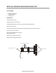
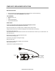
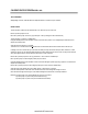

R ep la cin g the O N /O F F S w itch
W r iting o n
TO P
W H IT E W IR E S
B LA C K W IR E S
FR O M
P O W ER S U PP LY
TO C IR C U IT
B O A R D
To ols R eq u ire d:
Pliers
C autio n: To avo id electric sho ck unplug the u nit befo re beg inn ing this
procedu re.
1. Tu rn th e P ow er S w itch O FF and un plug u nit fro m w all outlet.
2. R em ove the C on trol Bo x Co ver. (5 P hillips S crew s)
3. U np lu g the the 2 w hite and 2 black w ires fro m th e b ack o f the
O N /O FF sw itch .
4. U se the pliers to sq ueeze the fastening clips an d pu sh the sw itch o ut.
5. Press the n ew O N /O F F sw itch into p ositio n.
6. Plug in th e W H ITE and B L A CK w ires as indica ted above .(Se e
illustration )
7. R ep lac e th e co ver.
FA S TE N IN G
C LIP S
Toll F re e 800.2 7 3.5 2 3 3 614.871.1 4 70 F a x : 614.871.1470
To:______________________________________________
C o m p any:_______ _________________________________
F ax:_____________________________________________
1 /9 /0 3 LM
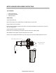
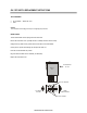
ON / OFF SWITCH REPLACEMENT INSTRUCTIONS
TOOLS REQUIRED:
On / Off Switch — Reorder No. 1507
Pliers
Caution:
To avoid electric shock unplug the unit prior to beginning this procedure.
INSTRUCTIONS:
Turn the Power Switch off and unplug unit from the wall outlet.
Remove the Control Box Cover. (5 Phillips Screws or 4 Phillips Screws for newer models).
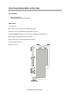
Unplug the two (2) white and two (2) black wires from the back of the On/Off Switch.
Use the pliers to squeeze the fastening clips and push the switch out.
Press the new On/Off Switch into position.
Plug in the white and black wires as indicated (see illustration).
Replace the Control Box Cover.
www.ActiveForever.com