Continuous Passive Motion Device (CPM) Operator Manual Phoenix Model 1800 Knee CPM Phoenix Model 1850 Knee CPM DC2480 Knee CPM www.ActiveForever.
FOREWARD This manual has been written for operators of the Furniss Corporation Continuous Passive Motion (CPM) Therapy Unit. It contains general information for operation, precautionary instructions and maintenance recommendations. In order to obtain maximum life and efficiency from your Furniss Corp CPM Unit, and to assist in the proper operation of the unit, read and understand this manual thoroughly.
PRECAUTIONARY INSTRUCTIONS CAUTION Read, understand and practice the precautionary instructions found in this manual before operating or using the unit. Know the limitations and hazards associated with using the device. Observe any and all precautionary and operational labels placed on the unit. Do not use the Furniss Corp CPM device outdoors or on wet surfaces. Use only on firm, flat, level surfaces to ensure stability of the unit while in operation.
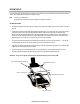
UNPACKING YOUR CPM When receiving your Furniss Corp CPM, examine the container and unit and report any substantial damage to the shipper. Do not discard your shipping container - it provides required protection for your unit during shipping and must be used when returning your unit for any warranty service. Unapproved or badly damaged containers will be replaced and billed accordingly. Container Contents > > > > > CPM Shipping Carton No.
SOFTGOODS APPLICATION Furniss Softgoods 1828-1 are designed specifically for use with Furniss Knee CPM devices. Softgoods provide a 'troughing' effect allowing proper alignment of the limb and a truer fit overall. Constructed with the highest quality materials. Furniss Softgoods provide superior comfort and support for the patient.
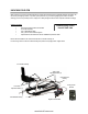
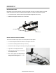
PATIENT SETUP Correct measurement and adjustments are required to ensure patient comfort and compliance and to achieve desired range of motion. Check that the unit is at 0 degrees during patient setup. Note: Use only on a stable surface. An unstable surface could result in injury to patient and damage to the device. FITTING THE PATIENT Determine the length of the patient’s femur by measuring from the greater trochanter (hip joint) to the center or joint line of the knee.
PATIENT SET UP BED STABILIZING SYSTEM Bed stabilizer rods are included in the base of each Furniss Knee CPM. This system, in conjunction with the non-skid pad located on the bottom of the control box, effectively prevents migration or "movement" of the unit while on a patient. Loosen the base knobs, extend the rods to the appropriate length and tighten the knobs securely. Stabilize the rods against a solid barrier such as a foot board.
OPERATING THE PHOENIX MODEL 1850 AND DC2480 CPM POWER ON AND OFF The ON/OFF switch is located at the base of the black control box. When the unit is powered ON it will beep one (1) time and the hand-held control pendant will illuminate. This indicates that the unit is ready for use.
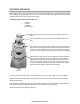
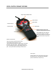
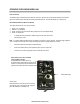
DIGITAL CONTROL PENDANT OVERVIEW Range of Motion (ROM) window Flexion window Flexion button Extension window Speed button Extension button Patient must have access to the hand-held control pendant at all times. *Pause button The Stop/Start button allows patient to stop the unit as needed. As a safety feature, the unit will travel in the opposite direction when the button is depressed again.
OPERATING THE PHOENIX MODEL 1800 Power On and Off The ON/OFF switch is located at the base of the black control box. When the unit is powered ON it will beep 3 times and the green power indicator light on the hand-held control pendant will illuminate. This indicates that the unit is ready for use. Phoenix Model 1800 Knee CPM Control Pendant The control pendant consists of four (4) control knobs: 1. 2. 3. 4.
MAINTENANCE Recommended Tools Small Phillips Screwdriver 1/8 T Handle Allen Wrench Basic Volt Meter Small Flat Head Screwdriver 3/32 T Handle Allen Wrench Light Building Grease (front end cap roller bearing) Phillips Screwdriver Red Loctite (shoulder bolt/acorn nut/calf + thigh tube bolt) 9/64 T Handle Allen Wrench Large Flat Head Screwdriver 5/32 T Handle Allen Wrench Blue Loctite (strut support bolt/set screws on pulleys + couplings) Small Needle Nose Pliers 3/4 Wrench (pendant cable/knee pot s
MAINTENANCE Track Seal Maintenance Track seals serve to protect each ball screw component. If the track seal is ripped or torn, it must be replaced. A damaged track seal allows large particles to enter the ball screw assembly, thus causing the unit to not operate properly. Remove the dry adhesive from the unit before continuing. Replace the track seal following instructions provided with the part. The best adhesive to use is a product that is 100% silicone, which is available for purchase from Furniss Corp.
MOTOR ONLY PREVENTIVE MAINTENANCE INSTRUCTIONS TOOLS REQUIRED: Phillips Head Screwdriver 9/64th Allen Wrench Compressed Air INSTRUCTIONS: Turn the power to the unit off. Unplug the motor from the circuit board. Using the 9/64 Allen Wrench remove the allen screws that hold the Drive Assembly. Remove the Drive Assembly. Loosen the Phillips Head Screws enough to create a gap between the three (3) sections of the motor. Caution: Do not remove the screws. ll F rethe e three 80 0(3) .2gaps 7 3.
MOTOR & GEARBOX REPLACEMENT INSTRUCTIONS To ll F re e 80 0 .2 7 3.5 2 3 3 6 1 4 .87 1 .1 4 70 F a x : 61 4 .8 7 1.1 4 7 0 TOOLS REQUIRED: Phillips Head Screwdriver R e p la c in g Small Flat Head Screwdriver 9/64th Allen Wrench th e M o to r & G e a rb o x To o ls req u ired : INSTRUCTIONS: P h illip s H ead S crew d riv er, S m all F lat H ead S crew d riv er, 9 /6 4 th A llen W ren ch Turn the Power Switch OFF. 1 . Tu rn th e P ow er S w itch O F F. 2 .
POWER SUPPLY REPLACEMENT INSTRUCTIONS IMPORTANT NOTATIONS: New power supply may be tested using a multi-meter. Ensure that wires do not touch while testing. Verify that power supply is NOT PLUGGED IN during installation TOOLS REQUIRED: Reorder No. Skit 1511A Pliers Phillips Head Screwdriver Large Flat Head Screwdriver INSTRUCTIONS: CAUTION: To avoid electric shock unplug the unit before beginning this procedure. Turn the Power Switch OFF and unplug the unit from wall outlet.
TRACK SEAL REPLACEMENT INSTRUCTIONS TOOLS REQUIRED: Track Seal Kit — Reorder No. Skit 1707A Adhesive (100% silicon) Reorder Code. ‘Adhesive’ Non-Abrasive Adhesive Remover INSTRUCTIONS: Remove the old track seals. Clean off any adhesive residue from the old track seal. Surfaces must be cleaned thoroughly for the new track seal to adhere properly. Clean with a quality, non-abrasive adhesive remover such as Goo-Gone.
ON / OFF SWITCH REPLACEMENT INSTRUCTIONS TOOLS REQUIRED: On / Off Switch — Reorder No. 1507 Pliers Caution: To avoid electric shock unplug the unit prior to beginning this procedure. INSTRUCTIONS: Turn the Power Switch off and unplug unit from the wall outlet. Remove the Control Box Cover. (5 Phillips Screws or 4 Phillips Screws for newer models). Unplug the two (2) white and two (2) black wires from the back of the On/Off Switch. Use the pliers to squeeze the fastening clips and push the switch out.
CIRCUIT BOARD REPLACEMENT INSTRUCTIONS TOOLS REQUIRED: Phillips Head Screwdriver Small Non-magnetic Phillips Head Screwdriver INSTRUCTIONS: Turn the power off. Remove the top cover of the Control Box (4 Phillips Head Screws). Unplug the motor, power, pendant and knee potentiometer connectors. Using the non-magnetic screwdriver, remove the 4 screws holding the Circuit Board in place. Replace with the new board and secure with the 4 screws.
CALIBRATION PROCEDURE MODEL 1800 TOOLS REQUIRED: Straight Edge, Protractor, 3/32 Allen Wrench, Phillips Screwdriver, 2 Position Jumper, Voltmeter INSTRUCTIONS: Turn the machine off. Remove knee potentiometer cover. Remove top cover of the unit. Remove 2 position jumper from J5. Place the 2 position jumper on the zero (0) position pins 1 and 2 (Counting from the Foot Plate down) Turn the machine on. Listen for 2 audible beeps. Using the Start/Stop button on the Pendant move the unit into the zero position.
CALIBRATION PROCEDURE MODEL 1850 TOOLS REQUIRED: Straight Edge, Protractor, 3/32 Allen Wrench, Phillips Screwdriver INSTRUCTIONS: Turn power off Remove knee potentiometer cover Remove top cover from the unit Move SW1 slide switch located at the bottom left of the board from run to calibrate Using the up and down arrows move the unit to the zero position Use a straight edge to determine zero Look for these values on the hand control Ext.
CALIBRATION PROCEDURE MODEL DC2480 TOOLS REQUIRED: Straight Edge, Protractor, 3/32 Allen Wrench, Phillips Screwdriver INSTRUCTIONS: Turn power off Remove knee potentiometer cover Remove top cover from the unit Move SW1 slide switch located at the bottom left of the board from run to calibrate Using the up and down arrows move the unit to the zero position Use a straight edge to determine zero Look for these values on the hand control Ext.