FIR INVERSION TABLE ITEM# 5211/5212 OWNER’S MANUAL The specifications of this product may vary from this photo and are subject to change without notice. IRONMAN, IRONMAN TRIATHLON and M-DOT are registered trademarks of World Triathlon Corporation. This product is licensed by the IRONMAN TRIATHLON.
TABLE OF CONTENTS Warranty----------------------------------------------------------------------------------------------3 Warning Label Placement----------------------------------------------------------------------- 4 Important Safety Precautions------------------------------------------------------------------- 5 Electrical Safety------------------------------------------------------------------------------------ 6 Included Hardware--------------------------------------------------------------------------
ONE YEAR LIMITED WARRANTY Paradigm Health & Wellness, Inc. warrants to the original purchaser that this product is free from defects in material and workmanship when used for the purpose intended, under the conditions that it has been installed and operated in according to Paradigm’s Owner’s Manual. Paradigm’s obligation under this warranty is limited to replacing free of charge, any parts which may prove to be defective under normal home use.
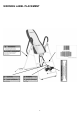
WARNING LABEL PLACEMENT 4
IMPORTANT SAFETY PRECAUTIONS Read all instructions carefully before assembling operating this product. Retain this owner’s manual and keep the original purchase receipt for future reference. 1. Consult your physician or other health care professionals before using the inversion table. 2. Always wear proper exercise apparel when using the equipment. 3. If any time you feel faint, light-headed or dizziness while operating the equipment, stop exercise immediately.
ELECTRICAL SAFETY When using the far infrared foam bed, basic precautions should always be followed, including the following: Read all instructions before using this unit. DANGER - To reduce the risk of electric shock: WARNING - To reduce the risk of burns, fire, electric shock, or injury to persons: 1. The far infrared foam bed should never be left unattended when plugged in. Unplug from outlet when not in use and before cleaning. 2.
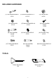
INCLUDED HARDWARE (11) Hex Head Bolt M6x47 2 PCS (16) Lock Nut M6 2 PCS (39) Hex Head Bolt M8x50 2 PCS (13) Washer Ø20xØ8.5x1.5 12 PCS (15) Lock Nut M8 6 PCS (27) Washer Ø16xØ6.5x1.0 4 PCS (42) Nut Cap Ø27xØ13.5 2 PCS (47) Phillips Bolt M6x20 4 PCS (53) Hex Head Bolt M8x38 2 PCS (38) Hex Head Bolt M8x23 2 PCS (43) Pivot Arm Ring 2 PCS (56) Washer Ø12xØ6.5x1.
OVERVIEW DRAWING 8
PARTS LIST Part# Description 001 Front U-Frame Quan. Part# Description 1 032 Nylon Strap Quan.
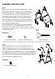
ASSEMBLY INSTRUCTIONS Step 1 Stand up the base of the machine by separating the frames. Pull the Front and Rear U-Frames (1, 2) as far apart from each others as possible. Then push down on the middle of the two Folding Arms (8) until they are fully locked down. Attach both Front Foot Caps (53) onto the Front Frame (1) with two Ø16xØ6.5x1.0 Washers (27) and M6x25 Bolts (51). Attach Left/Right Front Foot Caps (48, 49) onto the bottom of the Front U-Frame (1) with two M6x20 Phillips Bolts (47) and two Ø12xØ6.
Step 3 Slide the bottom of the Pivot Arms (5) into the brackets, located at each side of the Bed Frame (4), align to the desired hole on the arm with the peg on the bracket. Insert the peg into the hole to lock the pivot arm in place. It is recommended that you use the bottom hole on the pivot arm until you become more familiar with the equipment. ․․․․․․․․․․․․․․․․․․․․․․․․․․․․․․․․․․․․․․․․․․․․․․․․․․․․ Step 4 Install the Pivot Arm Rings (43) onto the Pivot Arms (5).
Step 5 Attach the top end of Handlebar (29) onto the Rear U-Frame (2) and Pivot Arm Ring (43) with one M8x23 Hex Head Bolt (38), one M8 Lock Nut (15), and two Ø20xØ8.5x1.5 Washers (13). Attach the bottom end of the Handlebar (29) onto The Rear U-Frame (2) with one M8x38 Hex Head Bolt (53), M8 Lock Nut (15), and two Ø20xØ8.5x1.5 Washers (13). Tighten bolts and nuts with two Wrenches provided. Repeat above same steps to attach the other Handlebar (29) onto the Rear U-Frame (2) and Pivot Arm Ring (43).
Step 6 Slide the Rod (9) through the large round hole on the side of Adjustable Boom (3), and secure the Rod (9) on the Adjustable Boom (3) with one M6x47 Hex Head Bolt (11), one M6 Lock Nut (16), and two Ø16xØ6.5x1.0 Washers (27). Slide one Steel Heel Holder Bracket (7) and one Rubber Rear Heel Holder (36) onto one end of the Rod (9) until the lock tooth is wedged into the slot in the Rod (9), as shown in detailed drawing.
Step 7 Slide the Foot Bar (60) into the bottom of the Adjustable Boom (3) and align two of the holes on the Foot Bar (60) with two holes on the boom. Secure the Foot Bar (60) in place using two M8x50 Hex Head Bolts (39), two M8 Lock Nuts (15), and four Ø20xØ8.5x1.5 Washers (13). Hardware: 2 Hex Head Bolts (M8x50) 4 Washers (Ø20xØ8.5x1.
Step 8 Remove the Square End Cap (40) on the back of square bracket of Adjustable Boom (3). Attach the Adjustable Instep Frame (6) to the Adjustable Boom (3) by inserting the Adjustable Instep Frame (6) into the square bracket on the boom. Slide the Adjustable Instep Frame (6) completely into the square bracket, insert the M6x47 Hex Head Bolt (11) with a Ø16xØ6.5x1.
Step 9 Pull out the Ball Spring Knob (18), and slide the Adjustable Boom (3) into the square bracket on the bottom of the Bed Frame (4) as shown. Slide the boom upward, until the desired height on the Height Scale (41) is just below the bracket on the bed frame. Lock the Adjustable Boom (3) in place by releasing the Ball Spring Knob (18) and sliding the Adjustable Boom (3) up or down slightly until the Ball Spring Knob (18) "pops" down into the locked position.
Step 11 Attach the Nylon and Loop Straps (32, 33) to the inversion table by hooking the end of the Loop Strap (33) to the pre-assembled loop on the back of the Bed Frame (4) as shown. Now hook the other end of Nylon Strap (32) to the other pre-assembled loop on the Front U-Frame (1) as shown.
ROUTING THE WIRE Route the wire as illustrated, place the Wire Holders (55) along the inner side of the frame approximately 10 inches apart, all the way close to the bottom of frame. Lead the Power Cord (54) through the protective cover all the way down. Use a Velcro Strap (58) to secure the Power Cord (54) to the Pivot Arm (5). Attach the wire by pressing it into the holders.
Caution: Wrong Routing Do not route the cable from outside of the handlebar. Caution: Wrong Routing The cable did not route through the axle of pivot arm first.
SAFETY OPERATING INSTRUCTIONS Incorrect Correct Pivot arm is NOT aligned correctly. The pivot arm is not inserted all the way into the curved slot. Make sure the pivot arm is inserted all the way into the slot. Pivot arm is aligned correctly when the groove sits directly on the curved slot and the pivot arm is able to rotate freely. WARNING: Please make sure both pivot arms are in the same hole to prevent serious injury from occurring.
OPERATION AND ADJUSTMENTS SHORTEN LENGTHEN THE STRAP For added safety, a nylon strap has been included to restrict the degree of inversion. This strap can be adjusted to different lengths to allow for a greater or lesser degree of inversion. To lengthen the Nylon Strap (32) feed the top end of Nylon Strap (32) into the strap lock, and pull on the lower end of the strap. To shorten the length feed the bottom end of Nylon Strap (32) into the strap lock, and pull on the top end.
PIVOT ARMS The Pivot Arms (5) can be adjusted to allow for a greater or lesser degree of inversion. To adjust the Pivot Arms (5) simply pull out on them until the post is out of the hole, slide them up or down to the desired hole, push in until the post goes through the desired hole. The bottom hole provides the least amount of inversion, while the top hole provides the greatest amount. It is recommended that beginners use the bottom hole until they are familiar with the inversion table.
GENERAL PRECAUTIONS 1. 2. 3. 4. 5. 6. Make sure that the Pivot Arms (5) are locks on the lowest hole for the first few attempts. It is recommended that someone be with you while you are using this inversion table for the first few times. Make sure that the Front and Rubber Rear Heel Holders (31, 36) are holding your feet securely. Make sure that the Adjustable Boom (3) is properly set to your height.
SUGGESTIONS FOR USE 1. 2. 3. 4. 5. Begin slowly: invert only 15~20 degrees to begin with. Stay inverted only as long as you are comfortable. Return upright slowly. Make gradual changes: increase the angle only if it is comfortable. Increase angle only a few degrees at a time. Increase the time of use 1~2 minutes up to ten over a period of weeks. Add stretching and light exercise only after you are comfortable with inversion.
STORAGE FOLDING THE INVERSION TABLE For your storage convenience, the inversion table can be folded down to place against a wall, under a bed, or in a storage area. To fold the inversion table pull out the Ball Spring Knob (18) and loosen Knob (30).
ABOUT TEMPERATURE 1. 2. 3. The temperature readout is based on the sensor built-in with the Fiber Glass Infrared heater mat inside. It does not represent the temperature of the cushion surface. Put a towel or cloth on top of the cushion will help increase the temperature even faster. After the 15-20 minutes preheat time, get on the inversion table and lay your back on the heat cushion, the temperature will continue to increase.
REMOTE CONTROL AND CONTROLLER OPERATION 1. 2. 3. 4. 5. 6. By default setting, when turned on, the temperature is set to 140 degrees F (60 degrees C), and timer is set to 40 minutes. This will ensure the far infrared foam bed heats up as quickly as possible. Adjust the temperature down to your desire setting after preheat. Set Low Heat at 100-110, Medium Heat at 120-130, or High Heat at 130-140 degrees F. The normal preheat time is 15-20 minutes, under room temperature at 68-77degrees F (20-25 degrees C).
WARM UP The WARM-UP is an important part of any workout. It should begin every session to prepare your body for more strenuous exercise by heating up and stretching your muscles, increasing your circulation and pulse rate, and delivering more oxygen to your muscles. HEAD ROLLS Rotate your head to the right for one count, feeling the stretch up the left side of your neck, then rotate your head back for one count, stretching your chin to the ceiling and letting your mouth open.
INNER THIGH STRETCH Sit with the soles of your feet together and your knees pointing outward. Pull your feet as close to your groin as possible. Gently push your knees toward the floor. Hold for 15 counts. TOE TOUCHES Slowly bend forward from your waist, letting your back and shoulders relax as you stretch toward your toes. Reach as far as you can and hold for 15 counts. HAMSTRING STRETCHES Extend your right leg. Rest the sole of your left foot against your right inner thigh.