Owner’s Operator and Maintenance Manual Tracer® IV Heavy Duty/Extra Wide DEALER: This manual MUST be given to the user of the product. USER: BEFORE using this product, read this manual and save for future reference. For more information regarding Invacare products, parts, and services, please visit www.invacare.
WARNING A QUALIFIED TECHNICIAN MUST PERFORM THE INITIAL SET UP OF THIS WHEELCHAIR. ALSO, A QUALIFIED TECHNICIAN MUST PERFORM ALL PROCEDURES SPECIFICALLY INDICATED IN THE MANUAL. DO NOT USE THIS PRODUCT OR ANY AVAILABLE OPTIONAL EQUIPMENT WITHOUT FIRST COMPLETELY READING AND UNDERSTANDING THESE INSTRUCTIONS AND ANY ADDITIONAL INSTRUCTIONAL MATERIAL SUCH AS OWNER’S MANUALS, SERVICE MANUALS OR INSTRUCTION SHEETS SUPPLIED WITH THIS PRODUCT OR OPTIONAL EQUIPMENT.
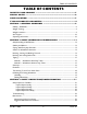
TABLE OF CONTENTS TABLE OF CONTENTS REGISTER YOUR PRODUCT ............................................................... 5 SPECIAL NOTES ................................................................................ 6 LABEL LOCATION ............................................................................ 7 TYPICAL PRODUCT PARAMETERS .................................................... 8 SECTION 1—GENERAL GUIDELINES ................................................... 9 Stability - All Models ........
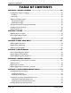
TABLE OF CONTENTS TABLE OF CONTENTS SECTION 4—FRONT RIGGINGS ........................................................ 26 Installing/Removing Front Riggings .......................................................................................................26 Installing..................................................................................................................................................26 Removing .................................................................................
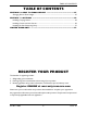
TABLE OF CONTENTS TABLE OF CONTENTS SECTION 10—SEAT TO FLOOR HEIGHT ............................................ 47 Changing Seat-to-Floor Height..............................................................................................................47 SECTION 11—OPTIONS ................................................................... 49 Installing Carrying Pocket .......................................................................................................................
SPECIAL NOTES SPECIAL NOTES Signal words are used in this manual and apply to hazards or unsafe practices which could result in personal injury or property damage. Refer to the following table for definitions of the signal words. SIGNAL WORD DANGER MEANING Danger indicates an imminently hazardous situation which, if not avoided, will result in death or serious injury. WARNING Warning indicates a potentially hazardous situation which, if not avoided, could result in death or serious injury.
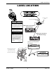
LABEL LOCATION LABEL LOCATION Lower Frame Tube Crossmember IMPORTANT NOTICE The wheel locks on this wheelchair have been pre-set at the factory to comply with the Veterans Administration functional Standard 8320.01 of the Federal Register, paragraph 3.2.4.5.3. If these wheel locks do not meet your needs, follow instructions below. ! Wheelchairs with Standard Wheel Package CAUTION Any wheel lock adjustments should embed wheel lock shoe at least 1/8" into tire when locked (3/16" on pneumatic tires).
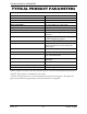
TYPICAL PRODUCT PARAMETERS 7 TYPICAL PRODUCT PARAMETERS TRACER IV OVERALL WIDTH 26¼ to 32¼ inches OVERALL DEPTH (WITHOUT RIGGINGS) 33½ inches SEAT WIDTH 18, 20, 22 or 24 inches SEAT DEPTH 18 and 20 inches SEAT-TO-FLOOR** 19½ inches (Adult), 17½ inches (Hemi) BACK STYLE Fixed BACK HEIGHT 16 inches ARM STYLES Fixed or Adjustable Height; Desk or Full Length; Removable FRONT RIGGINGS Swingaway Removable Footrests, Elevating Legrests, and Articulating Elevating Legrests REAR AXLE Permanent R
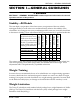
SECTION 1—GENERAL GUIDELINES SECTION 1—GENERAL GUIDELINES WARNING SECTION 1 - GENERAL GUIDELINES contains important information for the safe operation and use of this product. Stability - All Models CASTER SIZE CASTER POSITION WHEEL SIZE WHEEL POSITION ANTI-TIPPERS USER CONDITION The seat depth, size/position of the front casters, size/position of the rear wheels, anti-tipper model, as well as the user condition directly relate to the stability of the wheelchair.
SECTION 1—GENERAL GUIDELINES Anti-Tippers Anti-tippers are specific to the different seat-to-floor angles and/or seat-to-floor heights. Refer to the charts in Installing/Adjusting Anti-tippers on page 42 for correct usage and adjustment. If these requirements cannot be achieved, DO NOT use the wheelchair. Contact a qualified technician. If changing the seat-to-floor height with or without a change to seat-to-floor angle, the correct anti-tippers MUST be used to maintain a 1½ to 2-inch ground clearance.
SECTION 1—GENERAL GUIDELINES DO NOT attempt to ride over curbs or obstacles. Doing so may cause your wheelchair to tip over and cause bodily harm to you or damage to the wheelchair. DO NOT attempt to reach objects if you have to move forward in the seat. DO NOT attempt to reach objects if you have to pick them up from the floor by reaching down between your knees. DO NOT lean over the top of the back upholstery to reach objects behind you, as this may cause the wheelchair to tip over.
SECTION 2—SAFETY/HANDLING OF WHEELCHAIRS SECTION 2—SAFETY/HANDLING OF WHEELCHAIRS Safety/Handling of Wheelchairs Safety and handling of the wheelchair require the close attention of the wheelchair user as well as the assistant. This manual points out the most common procedures and techniques involved in the safe operation and maintenance of the wheelchair.
SECTION 2—SAFETY/HANDLING OF WHEELCHAIRS To assure stability and proper operation of your wheelchair, you MUST maintain proper balance at all times. Your wheelchair has been designed to remain upright and stable during normal daily activities as long as you DO NOT move beyond the center of gravity. Virtually all activities which involve movement in the wheelchair have an effect on the center of gravity.
SECTION 2—SAFETY/HANDLING OF WHEELCHAIRS Many activities require the wheelchair owner to reach, bend and transfer in and out of the wheelchair. These movements will cause a change to the normal balance, the center of gravity, and the weight distribution of the wheelchair. To determine and establish your particular safety limits, practice bending, reaching and transferring activities in several combinations in the presence of a qualified healthcare professional before attempting active use of the wheelchair.
SECTION 2—SAFETY/HANDLING OF WHEELCHAIRS Tipping WARNING DO NOT tip the wheelchair without assistance. When tipping the wheelchair, an assistant should grasp the back of the wheelchair on a non-removable (non-detachable) part. Inform the wheelchair occupant before tipping the wheelchair and remind him/her to lean back. Be sure the occupant’s feet and hands are clear of all wheels and/or pinch points.
SECTION 2—SAFETY/HANDLING OF WHEELCHAIRS NOTE: For this procedure, refer to FIGURE 2.4. This method requires two assistants. The second assistant should be positioned at the front of the wheelchair lifting upward on a non-removable (non-detachable) part of the wheelchair frame when lifting the wheelchair and stabilizing the wheelchair when the wheelchair is being lowered to the ground. The first assistant should stand on the sidewalk and turn the wheelchair so that the rear wheels are against the curb.
SECTION 2—SAFETY/HANDLING OF WHEELCHAIRS WARNING Extreme caution is advised when it is necessary to move an occupied wheelchair up or down the stairs. Invacare recommends that, if possible, the user be removed from the wheelchair prior to moving. Invacare recommends using two assistants and making thorough preparations. Make sure to use only secure, non-detachable parts for hand-held supports. NOTE: For this procedure, refer to FIGURE 2.5.
SECTION 2—SAFETY/HANDLING OF WHEELCHAIRS Transferring To and From Other Seats WARNING Before attempting to transfer in or out of the wheelchair, every precaution should be taken to reduce the gap distance. Turn both casters parallel to the object you are transferring onto. Also be certain the wheel locks are engaged to help prevent the wheels from moving.
SECTION 2—SAFETY/HANDLING OF WHEELCHAIRS Unfolding NOTE: For this procedure, refer to FIGURE 2.7. 1. Tilt the wheelchair toward you (raising the opposite wheel and caster off the ground/floor). 2. Place your hand on the top of the seat rail closest to you where the seat upholstery is attached. 3. Point your fingers and thumb to the inside of the wheelchair. 4. Press downward on the top of the seat rail until the wheelchair is fully open and the seat rails are fully seated in the H-blocks. 5.
SECTION 2—SAFETY/HANDLING OF WHEELCHAIRS CAUTION DO NOT allow upholstery to hang between the cross braces. 4. Continue to close the wheelchair by grasping the back cane furthest from you and pulling the armrest toward you. FIGURE 2.8 Folding Wheelchair NOTE: If the wheelchair is equipped with carry straps, the wheelchair may be closed by pulling up on the straps. Tracer® IV 20 Part No.
SECTION 3—SAFETY INSPECTION/TROUBLESHOOTING SECTION 3—SAFETY INSPECTION/TROUBLESHOOTING NOTE: Every six months or as necessary, take your wheelchair to a qualified technician for a thorough inspection and servicing. Regular cleaning will reveal loose or worn parts and enhance the smooth operation of your wheelchair. To operate properly and safely, your wheelchair MUST be cared for just like any other vehicle. Routine maintenance will extend the life and efficiency of your wheelchair.
SECTION 3—SAFETY INSPECTION/TROUBLESHOOTING ❑ Adjust rear wheel bearing system if wheel wobbles noticeably or binds to a stop. ❑ Ensure rear wheel bearings are clean and free of moisture. ❑ Ensure all spokes are uniformly tight. ❑ Inspect handrims for signs of rough edges or peeling. ❑ Inspect handrims for loose or missing hardware. ❑ Inspect axle assembly for proper tension by spinning caster. Caster should come to a gradual stop.
SECTION 3—SAFETY INSPECTION/TROUBLESHOOTING ❑ Adjust rear wheel bearing system if wheel wobbles noticeably or binds to a stop. ❑ Ensure rear wheel bearings are clean and free of moisture. ❑ Adjust front casters/forks bearing system if wheel wobbles noticeably or binds to a stop. ❑ Ensure wheel bearings are clean and free of moisture. Inspect/Adjust Periodically ❑ Ensure that the wheelchair rolls straight (no excessive drag or pull to one side). ❑ Inspect frame and crossbraces for loose or missing hardware.
SECTION 3—SAFETY INSPECTION/TROUBLESHOOTING Maintenance Maintenance Safety Precautions WARNING After any adjustments, repair or service and before use, make sure all attaching hardware is tightened securely. Otherwise injury or damage may result. CAUTION DO NOT overtighten hardware attaching to the frame. This could cause damage to the frame tubing. Suggested Maintenance Procedures 1. Before using your wheelchair, make sure all nuts and bolts are tight. Check all parts for damage or wear and replace.
SECTION 3—SAFETY INSPECTION/TROUBLESHOOTING 6. Hand grips should be checked monthly for wear/looseness/deterioration. Clean if desired. Replace if looseness or deterioration is found. 7. Check upholstery for sagging, rips or tears. 8. Replace any labels that are missing, worn, or torn. Refer to Label Location on page 7 for a listing of labels and their locations. Part No.
SECTION 4—FRONT RIGGINGS SECTION 4—FRONT RIGGINGS WARNING After any adjustments, repair or service and before use, make sure all attaching hardware is tightened securely. Otherwise injury or damage may occur. Installing/Removing Front Riggings NOTE: For this procedure, refer to FIGURE 4.1. Installing 1. Turn the front rigging assembly to the side (open front rigging is perpendicular to wheelchair). Front Rigging Release Lever 2.
SECTION 4—FRONT RIGGINGS Adjusting Footplate Height Spring Button Height NOTE: For this procedure, refer to FIGURE 4.2. NOTE: This procedure applies to the swingaway front riggings and swingaway elevating legrest. 1. Remove the front rigging assembly. Refer to Installing/Removing Front Riggings on page 26. NOTE: Lay the front rigging assembly on a flat surface to simplify this procedure. 2. Pull the cam lock lever up to unlocked position.
SECTION 4—FRONT RIGGINGS 5. Adjust the footplate assembly height by aligning the desired adjustment holes in the upper front rigging support and lower footplate assembly. 6. From the outside of the swingaway front rigging, insert the threaded rivet through both the front rigging support and the footplate assembly. 7. From the inside of the swingaway front rigging, insert the button head screw through the appropriate adjustment hole and thread into the threaded rivet. 8.
SECTION 4—FRONT RIGGINGS 1. To raise the elevating legrest, the assistant should hold the support tube and raise the elevating legrest until the desired height is obtained. Release Lever 2. To lower the elevating legrest, perform the following: A. Support user leg with one hand. B. Push release lever downward with other hand. C. Gently, lower user leg down and rest against the legrest. Support Tube FIGURE 4.
SECTION 4—FRONT RIGGINGS Replacing Heel Loop NOTE: For this procedure, refer to FIGURE 4.6 on page 31. 1. Pull the cam lock lever up to unlocked position. 2. Perform one of the following as shown in Detail "A". • Footplates with Spring Buttons: Push in the release buttons and remove the footplate assembly from the front rigging support. • Bolt-In-Place Footplates: i. Using a screw driver to hold the threaded rivet in position, remove the button head screw from the threaded rivet. ii.
SECTION 4—FRONT RIGGINGS DETAIL “A” Bolt-in-Place Footplates Footplates with Spring Buttons Adjustment Holes Cam Lock Lever Footplate Assembly NOTE: Swingaway footrest shown. Threaded Rivet Button Head Screw Front Rigging Support Release Button Front Rigging Support Front Rigging Support Cam Lock Lever Footplate Assembly Adjustment Hole Footplate Assembly Inside of Swingaway Front Rigging Mounting Screw Outside of NOTE: Swingaway Swingaway footrest shown.
SECTION 5—ARMS SECTION 5—ARMS NOTE: Tracer IV wheelchairs are equipped with fixed height armrests as standard equipment. Adjustable armrests are available on Tracer IV wheelchairs as an option. WARNING After any adjustments, repair or service and before use, make sure all attaching hardware is tightened securely. Otherwise injury or damage may occur. Adjusting Armrest Height WARNING Locked (Vertical) Make sure the height adjustment lever is in the locked position before using the wheelchair.
SECTION 5—ARMS Removing Armrest 1. Push down on armrest to ensure it is fully seated in front and rear sockets. NOTE: STEP 1 prevents the release buttons from hanging up on the sockets during removal. 2. Unlock the rear armrest by rotating the armrest release lever towards the inside of the wheelchair. 3. Press in the armrest release button at the front of the armrest. 4. While pressing in the armrest release button, remove the armrest from the arm sockets by pulling straight up.
SECTION 6—SEAT AND BACK SECTION 6—SEAT AND BACK WARNING After any adjustments, repair or service and before use, make sure all attaching hardware is tightened securely. Otherwise injury or damage may occur. Replacing Back Upholstery NOTE: For this procedure, refer to FIGURE 6.1. 1. Remove the eight mounting screws and washers that secure the existing back upholstery to the back canes. Washers Back Upholstery 2. Remove existing back upholstery from the back canes. 3.
SECTION 6—SEAT AND BACK Adjusting the Seat Width NOTE: For this procedure, refer to FIGURE 6.3 on page 36. NOTE: When adjusting the seat width of the wheelchair, the back and seat upholstery MUST be changed. If applicable, the headrest pillow and headrest upholstery MUST be changed as well. 1. Remove the existing back and seat upholstery from the wheelchair. Refer to Replacing Back Upholstery and Replacing Seat Upholstery on page 34. 2.
SECTION 6—SEAT AND BACK Hex Screws Locknut (For Pivot Link) Locknut Button Screws Pivot Link Wheelchair Frame Crossbrace (Bottom) Locknut Locknuts Button Screw Crossbrace Saddles FIGURE 6.3 Adjusting the Seat Width Tracer® IV 36 Part No.
SECTION 7—REAR WHEELS SECTION 7—REAR WHEELS WARNING After any adjustments, repair or service and before use, make sure all attaching hardware is tightened securely. Otherwise injury or damage may occur. Removing/Installing Rear Wheels WARNING Only a qualified technician may change the seat-to-floor height. Install only 24-inch rear wheels on the Tracer IV wheelchair. Otherwise, the wheelchair will become unstable and injury or damage may occur.
SECTION 7—REAR WHEELS Replacing Rear Wheel Handrim NOTE: For this procedure, refer to FIGURE 7.2. Rear Wheel Mounting Screw 1. Remove the rear wheel from the wheelchair. Refer to Removing/Installing Rear Wheels on page 37. 2. Remove the mounting screws and washers (not shown) that secure the handrim to the rear wheel. 3. Remove the existing handrim. Handrim 4. Install the new handrim by reversing STEPS 1-3. FIGURE 7.2 Replacing Rear Wheel Handrim 5. Reinstall rear wheel to the wheelchair.
SECTION 8—FRONT CASTERS SECTION 8—FRONT CASTERS WARNING After any adjustments, repair or service and before use, make sure all attaching hardware is tightened securely. Otherwise injury or damage may occur. Installing/Replacing Front Casters and Forks WARNING Make sure both fork/caster assemblies are the same size before using the wheelchair. Otherwise injury may occur. NOTE: For this procedure, refer to FIGURE 8.1. NOTE: This procedure can be performed if replacing the exact same size front caster.
SECTION 8—FRONT CASTERS Adjusting Forks 1. To properly tighten caster journal system and guard against flutter, perform the following check: A. Tip back of wheelchair to floor. B. Pivot both forks and casters to top of their arc simultaneously. C. Let casters drop to bottom of arc (wheels should swing once to one-side, then IMMEDIATELY rest in a straight downward position). D. Adjust locknuts according to freedom of caster swing. E.
SECTION 8—FRONT CASTERS Locknut Fork Hex Screw Washer (if applicable) Front Caster Washer (if applicable) FIGURE 8.2 Replacing Front Casters Replacing/Repairing Front Caster Tire/Tube WARNING Replacement of front caster tire MUST be performed by a qualified technician. CAUTION As with any vehicle, check the wheels and tires periodically for cracks and wear. Replace if damaged. Part No.
SECTION 9—ANTI-TIPPERS/WHEEL LOCKS SECTION 9—ANTI-TIPPERS/WHEEL LOCKS WARNING After any adjustments, repair or service and before use, make sure all attaching hardware is tightened securely. Otherwise injury or damage may occur. Installing/Adjusting Anti-tippers WARNING Anti-tippers are specific to the different seat-to-floor angles and/or seat-to-floor heights. Refer to the chart in this section of the manual for correct usage and adjustment.
SECTION 9—ANTI-TIPPERS/WHEEL LOCKS Wheelchair Model TRACER IV Anti-Tipper (in inches) Seat-to-Floor Height (in inches) Length Height Model Part No. 17½ to 19½ 13½ 3¼ 1360 1058836 DETAIL “A” DETAIL “B” Anti-Tipper Height Anti-Tipper Wheels Flat Surface Anti-Rattle Anti-Tipper Release Buttons Anti-Tipper Length Rear Frame Tubing FIGURE 9.1 Installing/Adjusting Anti-tippers - Anti-Tipper Length 1.
SECTION 9—ANTI-TIPPERS/WHEEL LOCKS 6. If the distance between the bottom of anti-tipper wheels and the ground/floor is not 1½ to 2-inches, repeat STEPS 2-5 until the distance is 1½ to 2-inches. Release Buttons 7. If the 1½ to 2-inch distance cannot be achieved with the anti-tippers, a different model may be required. Contact an Invacare dealer or qualified technician. 1½ to 2-inch Clearance FIGURE 9.
SECTION 9—ANTI-TIPPERS/WHEEL LOCKS Push wheel lock handle away from the tire to engage wheel lock Pull wheel lock handle toward the tire to disengage wheel lock Unlocked Position Locked Position Wheel Lock Wheel Lock Push-To-Lock Push wheel lock handle away from the tire to disengage wheel lock Pull wheel lock handle toward the tire to engage wheel lock Locked Position Unlocked Position Wheel Lock Pull-To-Lock Wheel Lock FIGURE 9.
SECTION 9—ANTI-TIPPERS/WHEEL LOCKS 7. Repeat the STEPS 1-6 until the wheel lock shoe embeds the tire 1/8-inch (3/16-inch for pneumatic tires) and holds the wheelchair. 8. If the measurement of 1/8-inch (3/16-inch for pneumatic tires) cannot be achieved, it may be necessary to install wheel lock shoe extensions. Refer to Installing Wheel Lock Shoe Extensions on page 46. DETAIL “A” 1/8-inch (3/16-inch pneumatic tires) Wheel Lock Shoe 9. Repeat STEPS 1-8 for the opposite wheel lock. Tire 10.
SECTION 10—SEAT TO FLOOR HEIGHT SECTION 10—SEAT TO FLOOR HEIGHT WARNING After any adjustments, repair or service and before use, make sure all attaching hardware is tightened securely. Otherwise injury or damage may occur. Changing Seat-to-Floor Height WARNING The size/position of the front casters, position of the rear wheels, use of anti-tipper model, as well as the user condition directly relate to the stability of the wheelchair.
SECTION 10—SEAT TO FLOOR HEIGHT 8-INCH FRONT CASTERS SEAT-TO-FLOOR HEIGHT (IN INCHES) FRONT CASTER MOUNTING POSITION REAR WHEEL SIZE REAR WHEEL MOUNTING POSITION 17½ Top 24-inch Top 19½ Bottom 24-inch Bottom DETAIL “A” - REAR WHEEL MOUNTING POSITIONS-ADULT/HE MI FRAME STYLE DETAIL “B” - 8-INCH FORK MOUNTING POSITIONS Top Top Bottom Middle Bottom FIGURE 10.1 Changing Seat-to-Floor Height Tracer® IV 48 Part No.
SECTION 11—OPTIONS SECTION 11—OPTIONS WARNING After any adjustments, repair or service and before use, make sure all attaching hardware is tightened securely. Otherwise injury or damage may occur. Installing Carrying Pocket NOTE: For this procedure, refer to FIGURE 11.1. 1. Determine the height required for the carrying pocket. 2. Remove the two back upholstery screws and two washers that correspond to the desired height. 3.
SECTION 11—OPTIONS Installing Crutch and Cane Carrier WARNING Check base weekly to ensure proper placement. When loading the crutch/cane carrier, ensure items are securely placed into the base. Also ensure that there is no interference with folding the wheelchair, the rear wheels, or the swing-back arms. Strap MUST be securely fastened while carrying items. NEVER insert or remove items while wheelchair is moving. NOTE: For this procedure, refer to FIGURE 11.2. 1.
SECTION 11—OPTIONS Installing the Seat Positioning Strap WARNING ALWAYS wear your seat positioning strap. Inasmuch as the seat positioning strap is an option on this wheelchair (you may order with or without the seat positioning strap), Invacare strongly recommends ordering the seat positioning strap as an additional safeguard for the wheelchair user. The seat positioning strap is a positioning strap only.