Owner’s Operator and Maintenance Manual Pronto ® M41 with SureStep ® DEALER: This manual MUST be given to the user of the wheelchair. USER: BEFORE using this wheelchair, read this manual and savefor future reference.
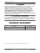
REFERENCE DOCUMENTS WARNING A qualified technician MUST perform the initial set up of this wheelchair. Also, a qualified technician MUST perform all procedures in the service manual. DO NOT use this product or any available optional equipment without first completely reading and understanding these instructions and any additional instructional material such as owner’s manuals, service manuals or instruction sheets supplied with this product or optional equipment.
TABLE OF CONTENTS TABLE OF CONTENTS REFERENCE DOCUMENTS ................................................................. 2 SPECIAL NOTES ................................................................................ 6 LABEL LOCATION ............................................................................ 8 TYPICAL PRODUCT PARAMETERS .................................................... 9 SECTION 1—GENERAL GUIDELINES .................................................
TABLE OF CONTENTS TABLE OF CONTENTS SECTION 7—ARMS ......................................................................... 34 Removing/Installing the Arms ................................................................................................................34 Adjusting the Arms ..................................................................................................................................35 SECTION 8—SEAT ........................................................................
TABLE OF CONTENTS TABLE OF CONTENTS SECTION 13—BATTERIES ................................................................ 58 Warnings For Handling and Replacing Batteries ...............................................................................58 Using the Proper Batteries.....................................................................................................................58 Removing/Installing the Batteries...............................................................................
SPECIAL NOTES SPECIAL NOTES Signal words are used in this manual and apply to hazards or unsafe practices which could result in personal injury or property damage. Refer to the table below for definitions of the signal words. SIGNAL WORD MEANING DANGER Danger indicates an imminently hazardous situation which, if not avoided, will result in death or serious injury. WARNING Warning indicates a potentially hazardous situation which, if not avoided, could result in death or serious injury.
SPECIAL NOTES WARNING The following warnings apply specifically to the SureStep Feature. • DO NOT use on inclines greater than 7°. • DO NOT use on inclines with wet, slippery, icy or oily surfaces. This may include certain painted or otherwise treated wood surfaces. • DO NOT traverse down ramps at high speed. Doing so will reduce traction and increase stopping distance. • The end user’s weight can substantially affect traction on sloped surfaces. Great care should be taken when traversing such slopes.
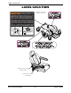
LABEL LOCATION LABEL LOCATION The POSITIVE ( + ) RED Battery Cable MUST connect to the POSITIVE (+) Battery Terminal(s)/ Post(s). The NEGATIVE (-) BLACK Battery Cable MUST connect to the NEGATIVE (-) Battery Terminal(s)/Post(s). DO NOT allow Battery Cable(s) to contact the opposite Battery Terminal(s)/Post(s). Install protective caps on POSITIVE (+) and NEGATIVE (-) battery terminals. Replace cable(s) immediately if cable(s) insulation becomes damaged.
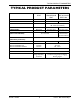
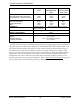
TYPICAL PRODUCT PARAMETERS TYPICAL PRODUCT PARAMETERS FOLD-DOWN SEAT OFFICE STYLE SEMI-RECLINE SEAT SEMI-RECLINE SEAT W/ SOLID SEAT PAN SEAT WIDTH: 18 inches SEAT DEPTH: 17 inches BACK HEIGHT: 16 inches BACK ANGLE RANGE: 95° Fixed 92 - 115° 90 - 114° UPHOLSTERY: Black Vinyl Dark Grey Vinyl Light Grey Vinyl SEAT-TO-FLOOR (WITH FOOTBOARD) 16 - 20 inches 16 - 18 inches 23½ inches (w/ headrest) 18¾ inches (w/o headrest) 19 to 23 inches OVERALL WIDTH (WITHOUT JOYSTICK): OVERALL HEIGHT: OVER
TYPICAL PRODUCT PARAMETERS FOLD-DOWN SEAT OFFICE STYLE SEMI-RECLINE SEAT SEMI-RECLINE SEAT W/ SOLID SEAT PAN *WEIGHT W/O BATTERIES AND FOOTPLATE: W/BATTERIES (U1) AND FOOTPLATE: 110 lbs 161 lbs 124 lbs 175 lbs 129 lbs 180 lbs SHIPPING BASE W/O BATTERIES: BASE W/ BATTERIES SEAT: 80 lbs 130 lbs 30 lbs 80 lbs 130 lbs 44 lbs 80 lbs 130 lbs 49 lbs ARMRESTS: Adjustable Width, Angle, and Depth BATTERIES: Adjustable Width, Angle, and Height U1 - Quantity 2 WEIGHT LIMITATION: 300 lbs PERFORMANCE SPE
SECTION 1—GENERAL GUIDELINES SECTION 1—GENERAL GUIDELINES WARNING SECTION 1 - GENERAL GUIDELINES contains important information for the safe operation and use of this product. Controller Settings/Repair or Service Set‐up of the Electronics Control Unit is to be performed only by a qualified technician. The final adjustments of the controller may affect other activities of the wheelchair. Damage to the equipment could occur if improperly set‐up or adjusted.
SECTION 1—GENERAL GUIDELINES DO NOT engage or disengage the motor release levers until the power is in the Off position. DO NOT operate on roads, streets or highways. DO NOT climb, go up or down ramps or traverse slopes greater than 7°. DO NOT attempt to move up or down an incline with a water, ice or oil film. DO NOT attempt to drive over curbs or obstacles. Doing so may cause your wheelchair to turn over and cause bodily harm or damage to the chair.
SECTION 1—GENERAL GUIDELINES Batteries The warranty and performance specifications contained in this manual are based on the use of deep cycle gel cell batteries. Invacare strongly recommends their use as the power source for this unit. Carefully read battery/battery charger information prior to installing, servicing or operating your wheelchair. The use of rubber gloves is recommended when working with batteries.
SECTION 1—GENERAL GUIDELINES Grounding Instructions DO NOT, under any circumstances, cut or remove the round grounding prong from any plug used with or for Invacare products. Some devices are equipped with three‐prong (grounding) plugs for protection against possible shock hazards and fire.
SECTION 2—EMI INFORMATION SECTION 2—EMI INFORMATION WARNING CAUTION: IT IS VERY IMPORTANT THAT YOU READ THIS INFORMATION REGARDING THE POSSIBLE EFFECTS OF ELECTROMAGNETIC INTERFERENCE ON YOUR POWERED WHEELCHAIR.
SECTION 2—EMI INFORMATION WARNING Powered Wheelchair Electromagnetic Interference (EMI) Because EM energy rapidly becomes more intense as one moves closer to the transmitting antenna (source), the EM fields from hand-held radio wave sources (transceivers) are of special concern. It is possible to unintentionally bring high levels of EM energy very close to the powered wheelchair's control system while using these devices. This can affect powered wheelchair movement and braking.
SECTION 3—INITIAL SETUP SECTION 3—INITIAL SETUP WARNING After any adjustments, repair or service and before use, make sure that all attaching hardware is tightened securely - otherwise injury or damage may result. Before performing any maintenance, adjustment or service verify that On/Off switch on the joystick is in the Off position. Setup Checklist NOTE: For this procedure, refer to FIGURE 3.1. Follow the checklist below to ensure the wheelchair is properly setup before initial use.
SECTION 4—SAFETY/HANDLING OF WHEELCHAIRS SECTION 4—SAFETY/HANDLING OF WHEELCHAIRS “Safety and Handling” of the wheelchair requires the close attention of the wheelchair user as well as the assistant. This manual points out the most common procedures and techniques involved in the safe operation and maintenance of the wheelchair. It is important to practice and master these safe techniques until you are comfortable in maneuvering around the frequently encountered architectural barriers.
SECTION 4—SAFETY/HANDLING OF WHEELCHAIRS To assure stability and proper operation of your wheelchair, you must at all times maintain proper balance. Your wheelchair has been designed to remain upright and stable during normal daily activities as long as you do not move beyond the center of gravity. DO NOT lean forward out of the wheelchair any further than the length of the armrests. Coping With Everyday Obstacles NOTE: For this information, refer to FIGURE 4.1.
SECTION 4—SAFETY/HANDLING OF WHEELCHAIRS Pinch Points WARNING Pinch point may occur when adjusting the arm angle position (Detail “A”). Pinch point may occur when rotating the footboard assembly (Detail “B”). DETAIL “A” Pinch Point DETAIL “B” Pinch Point FIGURE 4.2 Pinch Points Lifting/Stairways WARNING DO NOT attempt to move an occupied power wheelchair between floors using a stairway. Use an elevator to move an occupied power wheelchair between floors.
SECTION 4—SAFETY/HANDLING OF WHEELCHAIRS Follow this procedure for moving the wheelchair between floors when an elevator is not available or lifting the wheelchair is necessary: NOTE: When using a stairway to move the wheelchair, seat and any accessories, move all wheelchair components away from the stairway prior to reassembly. NOTE: This procedure needs two assistants to lift the wheelchair to transport it. 1. Remove the occupant from the wheelchair. 2. Remove the seat.
SECTION 4—SAFETY/HANDLING OF WHEELCHAIRS Transferring To and From Other Seats WARNING ALWAYS turn the wheelchair power Off and engage the Motor Release Levers to prevent the wheels from moving before attempting to transfer in or out of the wheelchair. Also, make sure every precaution is taken to reduce the gap distance by aligning both the front and rear casters parallel with the object you are transferring onto. CAUTION When transferring, position yourself as far back as possible in the seat.
SECTION 4—SAFETY/HANDLING OF WHEELCHAIRS Reaching, Leaning and Bending - Forward NOTE: For this procedure, refer to FIGURE 4.5. Position the front and rear casters so that they are extended as far forward as possible and engage motor release levers. WARNING DO NOT attempt to reach objects if you have to move forward in the seat or pick them up from the floor by reaching down between your knees. FIGURE 4.
SECTION 5—SAFETY INSPECTION SECTION 5—SAFETY INSPECTION Safety Inspection Checklists CAUTION As with any vehicle, wheels and tires should be checked periodically for cracks and wear and should be replaced as necessary. Initial adjustments should be made to suit your personal body structure needs and preference. Thereafter follow these maintenance procedures: Inspect/Adjust Initially ❑ Ensure that the wheelchair rolls straight (no excessive drag or pull to one side).
SECTION 5—SAFETY INSPECTION Inspect/Adjust Weekly ❑ Seat is secured to wheelchair frame. ❑ Seat and/or back upholstery have no rips and DO NOT sag. Replace if necessary. ❑ Seat release latch is not worn and is functional. Replace if necessary. ❑ Inspect tires for flat spots and wear. ❑ Ensure that casters are free of debris. ❑ Ensure arm pivot points are not worn and/or loose. Replace if necessary.
SECTION 5—SAFETY INSPECTION Inspect/Adjust Periodically ❑ Ensure wheelchair rolls straight (no excessive drag or pull to one side). ❑ Ensure that casters are free of debris. ❑ Ensure arms are secure but easy to release and adjustment levers engage properly. ❑ Ensure adjustable height arms operate and lock securely. ❑ Ensure arm pivot points are not worn and/or loose. Replace if necessary. ❑ Ensure armrest pads sit flush against arm. ❑ Ensure seat and/or back upholstery have no rips and DO NOT sag.
SECTION 5—SAFETY INSPECTION SYMPTOM Wheelchair will not drive. PROBABLE CAUSE Motor release levers are disengaged. Batteries require charging. Charger plugged in. Circuit breaker tripped. SOLUTIONS Engage motor release levers. Charge batteries. Make sure the setting on the charger is correct. Unplug charger from wall outlet before operating the wheelchair. Reset circuit breaker. If breaker trips again, it may indicate need for internal repair. Contact Dealer/Invacare.
SECTION 5—SAFETY INSPECTION Information Gauge Display Diagnostics DISPLAY DESCRIPTION DEFINITION COMMENTS Information Gauge Display All LEDs are off. Power is off. All LEDs are on. Power is on. Fewer than three LEDs on implies reduced battery charge. Left RED LED is flashing. Battery charge is low. The batteries should be charged as soon as possible. Right to Left slow “Chase” Joystick is in lock mode. Press the horn button twice within 10 seconds to unlock joystick.
SECTION 6—WHEELCHAIR OPERATION SECTION 6—WHEELCHAIR OPERATION WARNING After any adjustments, repair or service and before use, make sure that all attaching hardware is tightened securely - otherwise injury or damage may result. Set-up of the Electronics Control Unit is to be performed only by a qualified technician. The final adjustments of the controller may affect other activities of the wheelchair. Damage to the equipment could occur if improperly set-up or adjusted.
SECTION 6—WHEELCHAIR OPERATION Using the Joystick to Drive the Wheelchair NOTE: For this procedure, refer to FIGURE 6.2. The joystick is located at the front of the joystick housing and provides smooth control of speed and direction. It is equipped with 360 degrees of mobility for ease of operation. The joystick is spring‐loaded, and automatically returns to the upright (neutral) position when released. Pushing the joystick in a given direction causes the wheelchair to move in that direction.
SECTION 6—WHEELCHAIR OPERATION MK5 SPJ-INT Joystick Switches and Indicators NOTE: For the following information, refer to FIGURE 6.3. Joystick Information Gauge Display On/Off Button Speedometer Bottom Left LED Increase Speed Button (Hare) Decrease Speed Button (Tortoise) DETAIL “A” FRONT VIEW Charger/ Programming Input Service Indicator FIGURE 6.3 MK5 SPJ-INT Joystick Switches and Indicators On/Off Button This button is located at the front of the joystick housing.
SECTION 6—WHEELCHAIR OPERATION Speed Control Buttons The speed control buttons (tortoise button ( adjust the maximum speed. ) and hare button ( )) are used to set and 1. To adjust the speed, perform one of the following: • Adjust Speed in 20% Increments (5 Speed Mode) ‐ Press the tortoise button ( ) or hare button ( ) to decrease/increase the speed in 20% increments. The larger bars in the speedometer will light. • Adjust Speed in Smaller Increments (VSP Mode) ‐ Perform the following steps: i.
SECTION 6—WHEELCHAIR OPERATION Service Indicator The AMBER service indicator will light when an error or fault occurs. Refer to Troubleshooting ‐ Electrical on page 29. Information Gauge Display Located on the front of the joystick housing, it provides the following information to the user on the status of the wheelchair ‐ 1. Power is on. 2. True state‐of‐battery‐charge, including notification of when the battery requires charging: A. GREEN LEDs ‐ Indicate well charged batteries. B.
SECTION 7—ARMS SECTION 7—ARMS WARNING After any adjustments, repair or service and before use, make sure that all attaching hardware is tightened securely - otherwise injury or damage may result. Before performing any maintenance, adjustment or service verify that On/Off switch on the joystick is in the Off position. Removing/Installing the Arms WARNING Increasing the width of the arms may affect the overall width of the wheelchair.
SECTION 7—ARMS Adjusting the Arms Adjusting Width NOTE: For this procedure, refer to FIGURE 7.2. 1. Loosen the two lock knobs that secure the arms to the arm support tube. NOTE: Both arms should be adjusted to the same distance away from the arm support tube. NOTE: Changing the width of the arms may also affect the overall width of the wheelchair. 2. Reposition the arms until desired width is achieved. 3. Securely tighten the two lock knobs that secure the arms to the arm support tube.
SECTION 7—ARMS Adjusting Height (Semi-Recline Seats Only) NOTE: For this procedure, refer to FIGURE 7.4. 1. Remove the lock knob that secures the armrest to the arm frame assembly. 2. Adjust the armrest to one of five positions. 3. Reinstall the lock knob that secures the armrest to the arm frame assembly and tighten securely. Height Adjustment Holes Armrest Arm Frame Assembly Lock Knob FIGURE 7.
SECTION 8—SEAT SECTION 8—SEAT WARNING After any adjustments, repair or service and before use, make sure that all attaching hardware is tightened securely - otherwise injury or damage may result. Before performing any maintenance, adjustment or service verify that On/Off switch on the joystick is in the Off position. Removing/Installing the Seat Assembly NOTE: For this procedure, refer to FIGURE 8.1. Removing 1. Disconnect the joystick. Refer to Disconnecting/Connecting the Joystick on page 56. 2.
SECTION 8—SEAT Adjusting the Back Angle (Semi-Recline Back) NOTE: For this procedure, refer to FIGURE 8.2. 1. Lift up on the release handle and adjust seat to desired angle. 2. Let go of the release handle to lock the back in position. Release Handle Office Style Van Seat FIGURE 8.2 Adjusting the Back Angle (Semi-Recline Back) Adjusting the Headrest NOTE: For this procedure, refer to FIGURE 8.3. 1. To raise the headrest, lift the headrest up to the desired position. 2.
SECTION 8—SEAT Replacing the Seat Positioning Strap WARNING ALWAYS wear your seat positioning strap. The seat positioning strap is a positioning belt only. It is not designed for use as a safety device withstanding high stress loads such as auto or aircraft safety belts. If signs of wear appear, belt MUST be replaced immediately. NOTE: For this procedure, refer to FIGURE 8.4. 1. Remove the two mounting screws that secure the seat positioning straps to the seat frame. 2.
SECTION 9—FOOTBOARD ASSEMBLY SECTION 9—FOOTBOARD ASSEMBLY WARNING After any adjustments, repair or service and before use, make sure that all attaching hardware is tightened securely - otherwise injury or damage may result. Before performing any maintenance, adjustment or service verify that on/off switch on the joystick is in the off position. DO NOT stand on the flip-up footboard. When getting in or out of the wheelchair, make sure that the flip-up footboard is in the upward position.
SECTION 9—FOOTBOARD ASSEMBLY DETAIL “A” - TOP VIEW OF FOOTBOARD Shroud Footboard Assembly Outer Edge of Tube Detent Balls Mounting Hole Quick Release Pin Quick Release Pin Detent Ball FIGURE 9.1 Removing/Installing the Footboard Assembly Adjusting the Footboard Assembly Angle NOTE: For this procedure, refer to FIGURE 9.2. 1. Loosen the jam nut and set screw located underneath on the backside of the footplate. 2. Adjust the set screw in or out to obtain the desired footboard assembly angle. 3.
SECTION 9—FOOTBOARD ASSEMBLY Depth NOTE: For this procedure, refer to FIGURE 9.3. 1. Remove the quick release pin that secures the footboard assembly to the wheelchair frame. WARNING Make sure the detent balls of the quick-release pin are fully released beyond the outer edge of the tube before operating the wheelchair. Otherwise, injury and/or damage may result. Keep detent balls clean 2. Adjust footboard to one of three mounting positions. 3. Install the quick release pin.
SECTION 9—FOOTBOARD ASSEMBLY Height NOTE: For this procedure, refer to FIGURE 9.4. 1. Remove the quick release pin that secures the footboard assembly to the wheelchair frame. 2. Remove the mounting bolt, sleeve, and locknut that secures the footboard to footboard support bracket. 3. Align the footbard to one of the mounting holes on the footboard support bracket. 4. Secure the footboard to the footboard support bracket with the mounting bolt, sleeve and locknut. Securely tighten.
SECTION 10—FRONT RIGGINGS SECTION 10—FRONT RIGGINGS WARNING After any adjustments, repair or service and before use, make sure that all attaching hardware is tightened securely - otherwise injury or damage may result. While the wheelchair is moving, minimum ground clearance for the front rigging is three inches. If the wheelchair is not moving, the front rigging MUST maintain a minimum of one inch ground clearance - otherwise personal injury and damage may result.
SECTION 10—FRONT RIGGINGS Removing 1. Push the front rigging release lever inward and rotate the footrest out. 2. Lift up on front rigging and remove from the wheelchair. 3. Repeat STEPS 1‐2 for opposite side of wheelchair. Adjusting Footrest Height Model PHWH93 NOTE: For this procedure, refer to FIGURE 10.2. 1. Remove any accessories from the footrest(s). 2. Remove the footrest from the wheelchair. Refer to Installing/Removing Front Riggings on page 44.
SECTION 10—FRONT RIGGINGS Model PH904A and PHAL4A NOTE: For this procedure, refer to FIGURE 10.3. NOTE: PH904A style front rigging shown. PHAL4A front rigging adjust the same way. 1. Loosen, but do not remove the lug bolt and locknut that secure the lower footrest to the footrest support. Footrest Support Lug Bolt 2. Reposition the lower footrest to the desired height. Locknut Lower Footrest 3. Securely tighten the lug bolt and locknut that secure the lower footrest to the footrest support.
SECTION 10—FRONT RIGGINGS Raising/Lowering Elevating Front Riggings NOTE: For this procedure, refer to FIGURE 10.5. Release Lever 1. Perform one of the following: • Raising ‐ Pull back on the release lever and raise front rigging to the desired height. • Lowering ‐ Support front rigging with one hand away from the release lever. Push release lever downward with other hand. FIGURE 10.
SECTION 10—FRONT RIGGINGS NOTE: The footplate will be on the inside of the wheelchair when locked in place. 4. Using the two socket bolts and locknuts, secure the telescoping front rigging support to the seat frame as shown in FIGURE 10.6. 5. If necessary, repeat STEPS 2‐4 on remaining telescoping front rigging support. 6. Reinstall the seat. Refer to Removing/Installing the Seat Assembly on page 37.
SECTION 11—SHROUD AND WHEELS SECTION 11—SHROUD AND WHEELS WARNING After any adjustments, repair or service and before use, make sure that all attaching hardware is tightened securely - otherwise injury or damage may result. Before performing any maintenance, adjustment or service verify that on/off switch on the joystick is in the off position. Replacing the Flat Free Tires on the Wheel Rim WARNING DO NOT attempt to replace flat free tires. This procedure MUST be performed by a qualified technician.
SECTION 11—SHROUD AND WHEELS Removing/Installing the Rear Shroud NOTE: For this procedure, refer to FIGURE 11.1. Removing 1. Remove the two screws that secure the rear shroud to the frame. 2. Remove the rear shroud. Installing 1. Insert the tabs at the bottom of the rear shroud into the slots in the bottom of the frame. 2. Secure the rear shroud to the frame using the two screws. DO NOT overtighten.
SECTION 11—SHROUD AND WHEELS Engaging/Disengaging Motor Release Lever WARNING DO NOT engage or disengage the motor release lever until the On/Off switch on the joystick is in the Off position. CAUTION Ensure both motor release levers are fully engaged before driving the wheelchair NOTE: For this procedure, refer to FIGURE 11.2 on page 51. NOTE: The motor lock disengagement/engagement allows freewheeling or joystick controlled operation.
SECTION 11—SHROUD AND WHEELS Removing 1. Remove the mounting screw, two spacers and locknut that secure the existing caster to the fork. 2. Remove the existing caster from the fork. Installing 1. Position the new/existing caster into the fork. Fork Locknut Mounting Screw 2. Reinstall the mounting screw, two spacers and locknut. Securely tighten. Spacer 3. Torque locknut to 10 ft‐lbs (120 in‐lbs). 4. Loosen the locknut 1/8 of a turn. 5. Move the caster side to side.
SECTION 11—SHROUD AND WHEELS Removing/Installing Forks and/or Caster Assemblies NOTE: For this procedure, refer to FIGURE 11.4. NOTE: Front and rear forks are replaced in the same manner. Removing 1. Remove the caster from the fork if necessary. Refer to Removing/Installing Casters on page 51. 2. Remove the head tube cap. 3. Remove locknut, washer and spacer securing the fork to the headtube. Installing 1. Insert threaded post of fork into headtube. NOTE: Check the bearing assemblies.
SECTION 12—ELECTRONICS SECTION 12—ELECTRONICS WARNING After any adjustments, repair or service and before use, make sure that all attaching hardware is tightened securely - otherwise injury or damage may result. Before performing any maintenance, adjustment or service verify that On/Off switch on the joystick is in the Off position. Removing/Installing the Joystick Assembly NOTE: For this procedure, refer to FIGURE 12.1 on page 55. Removing 1.
SECTION 12—ELECTRONICS Seat Joystick Joystick Mounting Tube Arm Mounting Bracket and Adjustment Lock Lever DETAIL “A” - STRAP LOCATIONS Seat Arm Mounting Screws Tie-wraps Here Joystick Joystick Cable FIGURE 12.1 Removing/Installing the Joystick Assembly Repositioning the Joystick NOTE: For this procedure, refer to FIGURE 12.2. NOTE: Take note of position and orientation of mounting hardware for reinstalling the joystick assembly. 1. Remove the joystick assembly from the wheelchair.
SECTION 12—ELECTRONICS Disconnecting/Connecting the Joystick NOTE: For this procedure, refer to FIGURE 12.3 on page 57 and FIGURE 11.1 on 50. Disconnecting the Joystick 1. Remove the joystick assembly from the wheelchair arm. Refer to Removing/Installing the Joystick Assembly on page 54. 2. Remove the seat. Refer to Removing/Installing the Seat Assembly on page 39. 3. Remove the tie‐wrap securing the joystick cable to the seat post. 4.
SECTION 12—ELECTRONICS DETAIL “A” Seat Left Motor Connector Joystick Battery Connector Right Motor Connector Joystick Cable FIGURE 12.3 Disconnecting/Connecting the Joystick Part No.
SECTION 13—BATTERIES SECTION 13—BATTERIES Warnings For Handling and Replacing Batteries WARNING After any adjustments, repair or service and before use, make sure that all attaching hardware is tightened securely - otherwise injury or damage may result. Before performing any maintenance, adjustment or service verify that On/Off switch on the joystick is in the Off position. Most batteries are not sold with instructions. However, warnings are frequently noted on the cell caps.
SECTION 13—BATTERIES WARNING Batteries with terminal configuration as shown below MUST be used. Batteries that have the reverse terminal configuration MUST NOT be used - otherwise injury and damage may occur. USE THIS CONFIGURATION U1 Battery DO NOT USE NEGATIVE (-) Battery Terminal U1 Battery POSITIVE (+) Battery Terminal NEGATIVE (-) Battery Terminal POSITIVE (+) Battery Terminal NOTE: Recommended battery type is spill proof and requires no maintenance except routine charging.
SECTION 13—BATTERIES 5. Disconnect the left battery from the right battery (RED and BLACK connectors). 6. Lift left and right battery out of the battery tray using the battery handles. Installing 1. Verify the joystick On/Off switch is in the Off position and disconnect joystick cable. Refer to Disconnecting/Connecting the Joystick on page 56. 2. Position the right battery in the battery tray. 3. Position left battery in the battery tray.
SECTION 13—BATTERIES Connecting/Disconnecting Battery Cables Connecting Battery Cables WARNING NEVER allow any of your tools and/or battery cable(s) to contact both battery terminal(s)/post(s) at the same time. An electrical short may occur and serious personal injury or damage may occur. The use of rubber gloves is recommended when working with batteries. WARNING DO NOT remove fuse or mounting hardware from POSITIVE (+) RED battery cable/mounting screw.
SECTION 13—BATTERIES 5. Secure each terminal cap in place with a tie‐wrap (use tie‐wraps 11‐1/2‐inches long) (Detail “B” of FIGURE 13.2). 6. Position the batteries into the wheelchair. Refer to Removing/Installing the Batteries on page 59. NOTE: New Battery(ies) MUST be fully charged before using, otherwise the life of the battery(ies) will be reduced. 7. If necessary, charge the batteries. Refer to Charging Batteries on page 63. DETAIL “A” NOTE: Battery terminal caps not shown on left battery for clarity.
SECTION 13—BATTERIES Disconnecting Battery Cables WARNING The use of rubber gloves is recommended when working with batteries. NEVER allow any of your tools and/or battery cable(s) to contact BOTH battery terminal(s)/post(s) at the same time. An electrical short may occur and serious personal injury or damage may occur. NOTE: For this procedure, refer to FIGURE 13.2 on page 62 and FIGURE 13.3 on page 63. 1. Remove the seat. Refer to Removing/Installing the Seat Assembly on page 37. 2.
SECTION 13—BATTERIES CAUTION New batteries MUST be fully charged prior to initial use of the wheelchair. ALWAYS charge new batteries before initial use or battery life will be reduced. As a general rule, you should recharge your batteries as frequently as possible to assure the longest possible life and to minimize required charging time. Plan to recharge them when you do not anticipate using the wheelchair.
SECTION 13—BATTERIES CAUTION Only use a charger approved by Invacare when charging through the joystick on this wheelchair model. DO NOT use an independent charger with an output rating of over 8A (Amps). Otherwise, damage may occur. NOTE: For this procedure, refer to FIGURE 13.4 on page 65. NOTE: The charger port located on the front of the joystick requires the use of an independent charger. 1. Attach the battery charger connector to the charger port on the front of the joystick. 2.
SECTION 14—ACCESSORIES SECTION 14—ACCESSORIES WARNING After any adjustments, repair or service and before use, make sure that all attaching hardware is tightened securely - otherwise injury or damage may result. Before performing any maintenance, adjustment or service verify that on/off switch on the joystick is in the off position.
SECTION 14—ACCESSORIES Installing/Removing the Oxygen Holder WARNING Contact your oxygen supplier for instructions in the use of oxygen. Extreme care MUST be exercised when us ing oxygen in close proximity to electric circuits. The Invacare oxygen holder is designed to be used in conjunction with oxygen cylinder models MD15 and ME24 only. To maintain safety, use only Invacare oxygen cylinder accessories (i.e. regulator, oxygen demand devices).
SECTION 14—ACCESSORIES Protective Caps Clamp Knob Welded Nut Clamp Knob Upper Support Clamp Knob Welded Nut Accessory Tube Mounting Tube Mounting Nut Lower Support Welded Nut Mounting Bolt Protective Caps Clamp Knob NOTE: Seat not shown. Mounting Hand Knob FIGURE 14.2 Installing/Removing the Oxygen Holder Installing/Removing/Using the Walker Holder INSTALLATION WARNINGS After any adjustments, repair or service and before use, make sure that all attaching hardware is tightened securely.
SECTION 14—ACCESSORIES Using the Walker Holder 1. Fold walker. Refer to instructions provided with the walker. NOTE: Walker MUST be folded before using walker holder. 2. Hang folded walker on walker holder hooks. 3. Secure walker with hook and loop straps. DETAIL “A” Seat Hook Walker Holder Accessory Tube Hook and Loop Straps Mounting Knob FIGURE 14.3 Part No.