
User guide
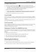
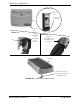
Table Of Contents
- Special Notes
- Register Your Product
- Typical Product Parameters
- Label Location
- Section 1— General Guidelines
- Section 2— Operation
- Installing the Mattress Replacement System
- Installing the Side Rails
- Installing the Power Unit
- Connecting the Hose
- Connecting the Power Cord
- Using the Front Panel
- Power Button
- Turn Button (MA90Z Power Unit)
- Turn Time Button (MA90Z Power Unit)
- Turn Angle Button (MA90Z Power Unit)
- Rotation Button (MA95Z Power Unit)
- Select Button (MA95Z Power Unit)
- Hold Button (MA95Z Power Unit)
- Firm/Soft Buttons
- Automatic Wireless Fowler
- Mode Button (MA90Z Power Unit)
- Max Inflate Button (MA95Z Power Unit)
- Lock/Alarm Silence Button
- Power Fail LED
- Low Pressure LED
- Displaying the Total Run Time (MA95Z Power Unit)
- Powering Up the System
- Placing the Patient on the Mattress
- Transferring Patient From/To a Gurney
- Transferring Patient From/To a Wheelchair
- Preparing for CPR Procedure
- Section 3— Maintenance and Troubleshooting
- LIMITED WARRANTY
SECTION 2—OPERATION
MA90 and MA95 Series Mattresses 22 Part No 1148139
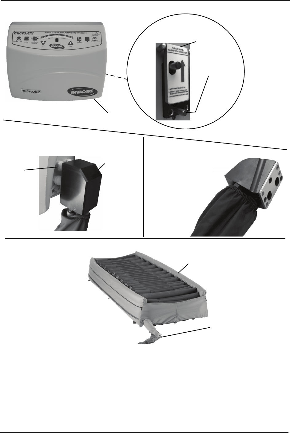
FIGURE 2.5 Preparing for CPR Procedure
Connector
Cover
Control Unit
Connectors
MA95Z,
MA95ZB42 and
MA95ZB48 Hose
Connector
DETAIL “A”
Control
Unit
RED CPR Connector
(MA90Z, MA90ZB42 and
MA90ZB48 Only)
Mattress
DETAIL “B”
DETAIL “D”
MA90Z,
MA90ZB42
and
MA90ZB48
Hose
Connector
Tab
DETAIL “C”