
User guide
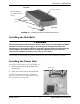
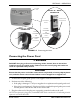
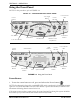
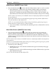
Table Of Contents
- Special Notes
- Register Your Product
- Typical Product Parameters
- Label Location
- Section 1— General Guidelines
- Section 2— Operation
- Installing the Mattress Replacement System
- Installing the Side Rails
- Installing the Power Unit
- Connecting the Hose
- Connecting the Power Cord
- Using the Front Panel
- Power Button
- Turn Button (MA90Z Power Unit)
- Turn Time Button (MA90Z Power Unit)
- Turn Angle Button (MA90Z Power Unit)
- Rotation Button (MA95Z Power Unit)
- Select Button (MA95Z Power Unit)
- Hold Button (MA95Z Power Unit)
- Firm/Soft Buttons
- Automatic Wireless Fowler
- Mode Button (MA90Z Power Unit)
- Max Inflate Button (MA95Z Power Unit)
- Lock/Alarm Silence Button
- Power Fail LED
- Low Pressure LED
- Displaying the Total Run Time (MA95Z Power Unit)
- Powering Up the System
- Placing the Patient on the Mattress
- Transferring Patient From/To a Gurney
- Transferring Patient From/To a Wheelchair
- Preparing for CPR Procedure
- Section 3— Maintenance and Troubleshooting
- LIMITED WARRANTY
SECTION 2—OPERATION
MA90 and MA95 Series Mattresses 14 Part No 1148139
Using the Front Panel
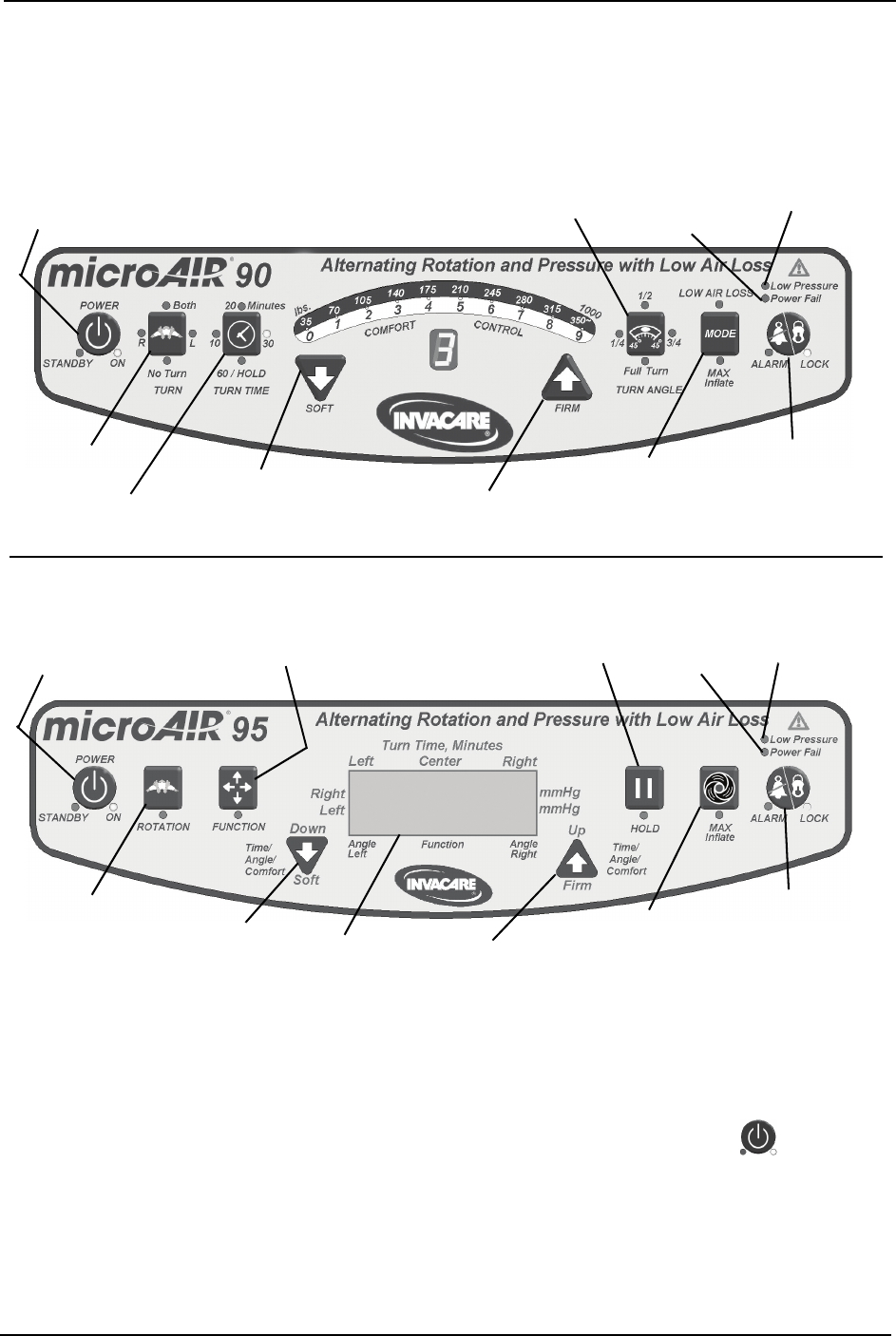
NOTE:Forthisprocedure,refertoFIGURE 2.4.
FIGURE 2.4 Using the Front Panel
Power Button
1. Toturnthecontrolunitonoroff,pressandreleasethePowerbutton().
NOTE:Oncetheunitispluggedin,anAMBERLEDonthecontrolunitislitindicatingthatthe
systemisinSTANDBYmode.OncethePowerbuttonispressedandreleased,aGREENLED
illuminatesindicatingthatthecontrolunitison.
Ifthepowercomesonafterapoweroutage,thecontrolunitwillgothroughitssysteminitializa‐
tionroutineforafewsecondsandthenresumethedesiredfunction.
DETAIL “B” - MA95Z POWER UNIT FRONT PANEL
Power
Button
Turn Button
Turn Time Button
Firm Button
Soft Button
Turn Angle
Button
Mode (Max
Inflate/Low Air
Loss) Button
DETAIL “A” - MA90Z POWER UNIT FRONT PANEL
Lock/Alarm
Button
Low Pressure
LED
Power
Fail LED
Power
Button
Rotation
Button
Select Button
Up/Firm Button
Down/Soft
Button
Hold
Button
Max Inflate
Button
Lock/Alarm
Button
Low Pressure
LED
Power
Fail LED
LCD