IMAGE EC POWER CHAIR IMAGE EC OWNER’S MANUAL
TABLE OF CONTENTS 1. PREFACE AND INTRODUCTION ……..………………………………… 2 2. SAFETY NOTICE………..…………………….................…… …………. Before driving While driving Labeling 3 3. EMI……………………………………………..……………………………….. 8 4. PARTS INTRODUCTION……………………………………………..………. 9 5. OPERATION………………………………………………………………….... 10 6. Joystick and controller How to operate your power chair How to set to freewheel mode BATTERY CHARGING AND CARE…………………………………….....
1. P R E FA C E A N D I N T R O D U C T I O N Please carefully read this owner’s manual before using the power chair. Improper use of the power chair could result in injury. This owner’s manual includes operating instructions for every aspect of the power chair, including assembly instructions and how to deal with possible accidents.
2. SAFETY NOTICE 2.1 BEFORE DRIVING The user should become familiar with the usage and operation of this power chair before driving. Therefore, please always keep the following safety notices in mind. ■ For your safety, please follow these safety instructions ◆ Drive on the pavement or pedestrian areas only. ◆ Do not drive your power chair after consuming alcohol or when tired. ◆ Please be careful when driving your power chair in low light. It is not been designed for use at night.
2. SAFETY NOTICE ■ Mobile Phones and Other Wireless Communication Devices ◆ Do not use a mobile phone or other wireless communication device while driving. ◆ Always stop and turn the power off before using a wireless communication device. ◆ Do not charge the mobile phone or any other electrical device from the power chair battery. ■ Automatic Power Shut Down In order to avoid accidental battery run down, your power chair is equipped with an automatic power shut down.
2. SAFETY NOTICE Warning! ◆ Do not set in the freewheel mode when driving on an incline or hill. ◆ Always re-engage the anti-freewheel device before use. Fail to do so may result in injury. ◆ Always fasten the seat belt when operating the power chair. ◆ To protect your safety, the power will automatically cut off and electromagnetic brake system will activate while driving down a steep incline or hill. This will limit the speed to a safe level. Turn the power on again to re-start your power chair.
2. SAFETY NOTICE Attention: When climbing an incline, do not zigzag or drive at an angle up the face of the incline. Always drive your power chair straight up the incline. This greatly reduces the possibility of a tip or a fall. Always exercise extreme caution when negotiating an incline. Never travel up or down an incline that is or covered by snow or ice. ■Inclines and uneven terrain When climbing an incline, try to keep your power chair moving.
2. SAFETY NOTICE This section provides the user with basic information that describes the problems with Electromagnetic interference (EMI), known sources of EMI, protective measure to either lessen the possibility or exposure or to minimize the degree of exposure, and suggested action should unexpected or erratic movement occur. Attention: It is very important that you read this information regarding the possible effects of Electromagnetic interference on your Image EC power chair.
3. EMI Attention: Other types of hand-held devices, such as cordless phones, laptop computers, AM/FM radios, TV sets, CD players, cassette and small appliances such as electric shavers and hair dryers are not likely to cause EMI problems with your power operated vehicle.
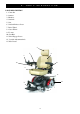
4. PA R T S I N T R O D U C T I O N PARTS DESCRIPTION 1. Controller 2. Armrest 3. Headrest 4. Seatback 5. Seat 6. Seatback Release Lever 7. Drive Wheel 8. Caster Wheel 9. Footrest 10. Seat Belt 11. Drive Engage Levers 12. Joystick Adjustment knob 13. Rear Casters 3 1. 2. 4. 12. 10. 5. 6. 11. 13. 9.
5. O P E R AT I O N JOYSTICK AND CONTROLLER Your Image EC is operated by a joystick and controller. The Image EC is currently available with the PG VR2 Controller. 2 1 6 4 VR2 Series CONTROL FUNCTIONS 1. ON/OFF Button 2. Battery Gauge 3. Joystick 4. Maximum Speed / Profile Indicator 5. Speed / Profile Decrease Button 6. Horn Button 7.
5. O P E R AT I O N Attention: We recommend that the first few times you operate your Image EC you set the speed adjustment button to the slowest setting until you become familiar with you new power chair. ◆ Speed / Profile Decrease Button This button decreases the maximum speed setting or, if the control system is programmed for drive profile operation, selects a lower drive profile. ◆ Horn Button Press either button to sound the horn.
5. O P E R AT I O N ■ JOYSTICK DEPTH ADJUSTMENT Your power chair may be equipped with an adjustable joystick. This function enables you to move the joystick from the armrest to the desired position. Suggestion 1. You should recharge the batteries after each time the power chair is used to ensure maximum range. The batteries should be charged at least once a week, even if the power chair is not used. 2.
5. O P E R AT I O N Warning When on an incline, NEVER switch the power chair to the freewheel mode. The electromagnetic brakes will not be applied and this may result in injury. HOW TO ADJUST THE SEAT ▇ To adjust the seatback angle ◆ Pull up the seatback release lever. ◆ Move the seatback down or up to the desired position . ◆ Release the seatback release lever. Seatback Release Lever ▇ To adjust the armrest width ◆ Loosen the knobs ◆ Slide the armrests in or out to the desired width .
5. O P E R AT I O N ▇ To adjust the armrests height ◆ Press the button. ◆ Move the armrest to the required position. Knob ▇ To adjust the headrest ◆ To raise headrest , lift it to the desired position. ◆ To lower headrest, push release tab towards the inside of the chair and lower the headrest to the desired position. Adjust the Headrest ▇ To remove the seat 1. Turn the power OFF. 2. Make sure the Image EC is not in freewheel mode. 3. Push the seat rotate lever while pulling up on the seat to remove.
5. O P E R AT I O N ▇ To change the seat height 1. Remove seat (See “To remove the Seat”) 2. Remove the shroud. 3. Disengage and remove the seat height adjustment bolt from the seat post. 4. Remove the height adjustment bolt from each of the three posts. 5. Raise or lower each post to the desired position. 6. Reinstall the seat height adjustment bolt through the seat post. 7. Reinstall the shroud. 8. Reinstall the seat.
5. O P E R AT I O N Warning Do not use your Image EC Power Chair while the drive motors are disengaged unless you are in the presence of an attendant! Do not disengage the drive motors when on an incline as the power chair may roll down, causing injury! Suggestion If a level is difficult to move in either direction, gently rock the power chair back and front; the level should then move to the desired position.
5.
6 . B AT T E RY C H A R G I N G A N D C A R E BATTERIES ◆ The Image EC Power Chair uses two long- lasting, 12 volt, deep-cycle batteries. These batteries are sealed and maintenance free. Since they are sealed, there is no need to check the electrolyte (fluid) level. Deep-cycle batteries are designed to handle a longer and deeper discharge. Though they are similar in appearance to automotive batteries, they are not interchangeable.
6 . B AT T E RY C H A R G I N G A N D C A R E ▇ To charge the batteries using the off-board charger ◆ Position the power chair next to a standard wall outlet. ◆ Be certain the controller power is turned off . ◆ Open the charging socket cap on the rear shroud .Then connect the charging cable into the charging socket. ◆ Plug the charging cable into the wall outlet. ◆ We also recommended that the batteries are not charged for more then 24 hours.
6 . B AT T E RY C H A R G I N G A N D C A R E ■ Cleaning the battery If the batteries are contaminated by water, battery acid, dust or other substances, they will discharge quickly. The batteries supplied with the power chair are sealed and as such are maintenance free with no risk of battery leakage. Please follow the steps below to clean the battery. 1. Turn the Image EC power switch to OFF. 2. Remove the seat. 3. Remove the shroud and unplug the terminal of the taillight and signal lights. 4.
7. INSPECTION AND MAINTENANCE INSPECTION Initial adjustments should be made to suit personal body structure and preference. Be sure to follow these checks and maintenance procedures. NO. 1 2 3 4 5 6 7 8 9 Item initially General(Mechanical Troubleshooting) ♦power chair rolls straight (no excessive drag or pull to one side). Arms ♦Secure but easy to release; adjustment levers engage properly. ♦Adjustable height arms operate and lock securely. ♦Pivot point free of wear and looseness.
7. INSPECTION AND MAINTENANCE REGULAR MAINTENANCE RECORD To make sure your power chair is correctly serviced, take it to your dealer for regular maintenance checks. The initial inspection should be made after the first month’s use, thereafter every six months. Your dealer may charge a fee for this.
7. INSPECTION AND MAINTENANCE Attention When tread depth is below 0.5mm it can easily lead to power chair slippage, making braking distances longer. Therefore replace the tyres as early as possible when they are found to have insufficient tread depth. Attention Before doing any maintenance, turn the power switch to OFF and remove the charger cords. Suggestions 1. Do not splash water onto the power chair as this could cause the electronic system to malfunction. 2.
8 . T R O U B L E S H O O T I N G A N D S P E C I F I C AT I O N ■ TROUBLE SHOOTING Symptom Probable cause Solution Limited driving distance ♦Batteries not fully charged. ♦Charge batteries overnight or ensure 10 hours of charge between uses. Make sure setting on charger is correct. Batteries not charging. ♦Batteries weak won’t hold charge. ♦Replace batteries ♦Charger not working ♦Replace charger. ♦Battery connections loose. ♦Check all connections. Secure connections. ♦No current at wall outlet.
8 . T R O U B L E S H O O T I N G A N D S P E C I F I C AT I O N SPECIFICTIONS MODEL IMAGE EC ITEM Dimension (L×W×H ) 41.75” x 24.6” x 43.25” / 1060x625x1100 mm Weight, with batteries Without batteries 192 lbs / 87 Kg 139 lbs / 63 Kg Battery 12V 36h×2 Motor 200W × 2 Charger DC24V 4A OFF-BOARD Front wheels 6.0“ × 2.0“ Solid / 150 × 50 mm Drive wheels 10.2“ × 3.3 “ Solid / 260 × 85 mm Anti-tip wheels 6.0“ × 2.
8 . T R O U B L E S H O O T I N G A N D S P E C I F I C AT I O N Self-Help Guide If a system trip occurs, you can find out what has happened by counting the number of bars on the battery gauge that are flashing. Overleaf is a list of self-help actions. Try to use this list before you contact your service agent. Go to the number in the list that matches the number Of flashing bars and follow the instructions. If the problem persists after you made the checks described above contact your service agent.
9. WARRANTY 9.1 WARRANTY There is a limited lifetime warranty on your new Image EC power chair. The warranty covers the power chair for parts only during this period. For more detail, please see the Warranty Conditions below. Warranty Conditions: Any work or replacement part installation must be carried out by an authorized Drive dealer / service agent. To apply the warranty should your power chair require attention please contact your service provider.
9. WARRANTY VIN (POWERCHAIR IDENTIFICATION NUMBER) To ensure the correct after sales, service and warranty service support, please write down the power chair identification number found on the rear right-hand side of the frame.