
User Manual


4. Turn the base over and set it on the floor.
5. Remove the tilt-locking hand nut from the motor connector and set aside.
6. Remove the bolt and knob, (main locking nut) small screw (this small screw is actually in the
motor assembly , not the post. It should be removed or backed all the way out in step 5) from
the top of the inner pipe and set aside.
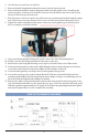
7. Place the motor connector onto the top of the inner pipe and insert the bolt through the square
hole of the motor connector. However, do not yet screw the knob (main locking nut) onto it.
8. Tighten the small screw fully into the motor connector, ensuring that it goes into the proper
hole (see image to verify the position).
9. Now screw the knob (main locking nut) onto the other side of the bolt and tighten it.
10. Finally, screw the tilt-locking hand nut into the motor connector.
11. Remove the outer back guard locking screws (4 pieces) from the front cover of the motor.
12. Position the back guard over the motor shaft, fitting the holes in the back guard over the four
screw holes on the outside of the motor. Make sure the handle is at the top.
13. Secure the back guard by screwing in the four back guard locking screws.
14. Loosen the securing screw on the pedestal fan blade. Slide the pedestal fan blade onto the
mounting shaft with the shaft sleeve facing the motor. Align securing screw with flat groove in
the motor shaft and tighten with a Philips screwdriver.
15. Remove the small securing bolt from the bottom of the front guard. Position front guard so the
logo is horizontal, and make sure the guard clips are open. Secure the top tab to the back guard.
Fasten the guards together with the securing bolt. Hold the front guard against the back guard
and snap the guard clips closed to complete the assembly.
ELECTRIC SCHEMATIC DIAGRAM
5