
User manual


NMEA 0183 Buffer - NBF-3
Page 13© 2013 Active Research Limited
Connecting Listeners to the NBF-3 Talker Ports
• Connect the NBF-3 Listener A/+ to the positive data line of the NMEA Talker.
• Connect the NBF-3 Listener B/- to the negative data line of the NMEA Talker. When connecting RS232 or NMEA
0183 version 1 Talkers, this will be the ground / common line of the Talker. Always check the manual for the correct
wiring.
Note: All six Talker port connections are identical. Any number of Talker ports can be used in any combination.
The NBF-3 can drive multiple Listeners from each Talker port. Check the input current requirements of each Listener
and ensure the combined total does not exceed the “Talker Output Current Drive”, see “Specications” on page 15.
Note: Each Talker port is fully isolated, but be aware that the NBF-3 will not provide isolation between multiple Listeners
connected to a single Talker port. Connecting more than one NMEA Listener is only recommended when all NMEA
Listeners are known to have isolated inputs.
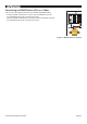
Figure 6 - Talker Port Wiring Diagram
Connecting an RS232 Device (PC) as a Listener
A PC can be connected the same way as an RS232 type NMEA Listener. The PC should be
connected as follows:
• Connect the NBF-3 Talker A/+ to the Rx pin of the RS232 connector.
On a standard 9 pin D-type connector, this is pin 2.
• Connect the NBF-3 Talker B/- to the Ground pin of the RS232 connector.
On a standard 9 pin D-type connector, this is pin 5.
Figure 7 - RS232 Listener Connection
®
Listener data: Negative
Listener data: Positive
Latitude
50˚74’03”
Longitude
-1˚94’95”
Listener data: Negative
Listener data: Positive
Listener Devices
5 14 3 2