
User manual


NMEA 0183 Buffer - NBF-3
Page 11© 2013 Active Research Limited
Connecting to the NBF-3 Listener Port
Connecting an NMEA Talker
The input to the NBF-3 is labelled ‘Listener’ and this is where the NMEA Talker should be connected.
• Connect the NBF-3 Listener A/+ to the positive data line of the NMEA Talker.
• Connect the NBF-3 Listener B/- to the negative data line of the NMEA Talker.
This is the ground / common connection of the Talker for RS232 or NMEA 0183 version 1 Talkers.
• For details on the data indicator, refer to “NBF-3 Listener Port Data LED (Green)” on page 14.
Note: Only one NMEA Talker can be connected to the NBF-3 Listener port. Multiple NMEA Talkers require an NMEA
Multiplexer to be tted, see www.actisense.com/NDC-4.
Note: The NMEA Listener port is fully isolated and is compatible with all versions of NMEA 0183 and with RS422,
RS232 and RS485 voltage levels, see “Specications” on page 15.
Powering the Talker from the NBF-3 Listener Port
It is also possible to power the NMEA Talker from the NBF-3. The NBF-3 power connection is routed to the Listener port
PWR OUT connection via a self-resettable fuse. A maximum of 500mA can be provided to the NMEA Talker at the
voltage supplied to the NBF-3.
• Connect the NBF-3 +VE OUT to the positive supply input of the NMEA Talker.
• Connect the GND OUT of the NBF-3 to the negative supply or ground input of the NMEA Talker.
Note: The current provided is temperature dependant, see “Specications” on page 15.
Note: If the NBF-3 power supply is incorrectly wired (reverse polarity), the Listener power output voltage will also be
reverse polarity and could potentially harm any connected equipment. However the NBF-3 electronics are always
protected against reverse polarity supply faults.
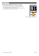
Figure 4 - Listener Port Wiring Diagram
®
Latitude
50˚74’03”
Longitude
-1˚94’95”
Talker power: Positive
Talker power: Negative
Talker data: Negative
Talker data: Positive
Talker Device