ScreenBeam Pro Wireless Display for Intel Pro WiDi Firmware: V2.11.x.x/V9.11.x.x User Manual V0.
Warning This device complies with part 15 of the FCC Rules. Operation is subject to the condition that this device does not cause harmful interference (1) this device may not cause harmful interference, and (2) this device must accept any interference received, including interference that may cause undesired operation. Changes or modifications not expressly approved by the party responsible for compliance could void the user's authority to operate the equipment.
Table of Contents Part I. Getting Started...................................................................................................................... 1 1.1. Contents in the Box ....................................................................................................... 1 1.2. Meeting ScreenBeam Pro ............................................................................................. 1 1.2.1. SBWD100BE02 ............................................................................
5.3.12. Setting up HDCP Encryption................................................................................ 42 5.3.13. Setting up the VGA Compatibility Mode ............................................................. 43 5.3.14. Setting up USB Local Access ................................................................................ 43 5.3.15. Adjusting TV Screen Size ..................................................................................... 44 5.3.16. Setting up Output Aspect Ratio ..
Part I. Getting Started Thank you for your purchase of Actiontec’s ScreenBeam Pro Wireless Display Receiver for Intel Pro WiDi (hereinafter refer to as “ScreenBeam Pro”). The Receiver lets you wirelessly stream what’s on your Intel WiDi or Miracast™ compatible device to your HDTV, including movies, videos, photos, music, and more. The Receiver frees your eyes from a tiny screen.
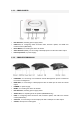
1.2.1. SBWD100BE02 l LED Indicator, indicating power supply status l USB Port, for configuring CMS connection data, firmware update, and USB over network control (UIBC/UoIP) l Reset Button, for resetting the device to default l Video Out Port (HDMI), for connecting to HDTV/projector for video and audio output l Power Input Port, for power supply 1.2.2.
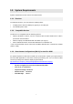
1.3. System Requirements System requirements for the receiver are shown below: 1.3.1. Receiver To install the Receiver, you must have the following items: l A display device with one HDMI port (Type A) or one VGA port l An available power outlet 1.3.2.
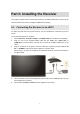
Part II. Installing the Receiver This chapter explains how to connect the Receiver to an HDTV. Make sure you have all the contents from the Receiver’s package available before starting. 2.1. Connecting the Receiver to an HDTV It is quite easy and fast to set up the Receiver. You can complete the connection in just one minute. To connect the Receiver to an HDTV: 1. Get the Receiver, AC power adapter, and HDMI cable from the Receiver’s package. 2.
The Receiver is connected to the HDTV, and it is ready for use. Note: Connections to other display devices are similar. 6. (Optional) VGA bypass connection is shown below: Note: The VGA bypass connection is for model SBWD950P/SBWD960A only.
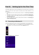
Part III. Setting Up for the First Time This chapter explains how to connect ScreenBeam Pro for the first time to the source device. There are several source device options: Intel WiDi (Intel Pro WiDi), Windows 8.1, and Windows 10. l For Windows 8.1 devices, please proceed to Section 3.1. Connecting via Windows 8.1; l For Windows 10 devices, please proceed to Section 3.2. Connecting via Windows 10; l For Windows 7/8 devices (Gen 4 WiDi), please proceed to Section 3.3.
3. From the Project menu, select Add a wireless display. Windows will search for available devices. Note: If you are running Windows 8.1 and the screens above do not appear, go to http://www.actiontec.com/widi81 for the latest software update. Or, you can update your Windows 8.1 via the Windows Update application. 4. Select your receiver from the device list. 5. A PIN entry box is displayed on the screen of your Windows 8.
6. Note: You should obtain the security PIN from your network administrator if no PIN is displayed on the connected display device. Your device will connect to the receiver within a few seconds.
Note: l Intel Pro WiDi (Gen 6) will run automatically if your device is compatible with Intel Pro WiDi (Gen 6) and has the app installed. l Your device’s screen will be displayed on the HDTV in about ten seconds if Intel WiDi (Gen 6)/Intel Pro WiDi (Gen 6) app is not installed on your device. Refer to 5.3.6. Setting up Inactive Source Grace Period for Managed Meetings for detail.
3.2. Connecting via Windows 10 This section explains how to connect a device running Windows 10 to ScreenBeam Pro. 1. Press the shortcut keys, Windows logo wireless display receiver list. + K, on your keyboard to display the Note: There are other ways to open the wireless display receiver list: l Click the Start button, and then select Settings > Devices > Connected devices > Add a device to open the wireless display receiver list.
3. A PIN entry box is displayed on the screen of your Windows 10 device, and a PIN code and host name (QA-PC01 in this example) of the connecting device are displayed on the HDTV. Type the PIN in the PIN entry box on your device, and then click Connect.
4. Note: You should obtain the security PIN from your network administrator if no PIN is displayed on the connected display device. Your device will connect to the receiver within a few seconds.
l Pro WiDi (Gen 6) and has the app installed. Your device’s screen will be displayed on the HDTV in about ten seconds if Intel WiDi (Gen 6)/Intel Pro WiDi (Gen 6) app is not installed on your device. Refer to 5.3.6. Setting up Inactive Source Grace Period for Managed Meetings for detail. 3.3. Connecting via Intel® WiDi App (Gen 4) This section explains how to connect a device running Intel's WiDi application to the receiver. Follow the procedure below to connect your device to the receiver: 1.
Note: You should obtain the security PIN from your network administrator if no PIN is displayed on the connected display device. 4. Within a few seconds, your device will connect to the receiver.
5. A "Connection Successful" screen appears on the device's screen. Click Finished, and the device’s screen will be displayed on the HDTV in about ten seconds.
3.4. Connecting via Intel® Pro WiDi App (Gen 6) ScreenBeam Pro supports Managed Meetings, which is only available with Intel® Pro WiDi. To use this feature, ScreenBeam Pro must have the AGO feature enabled. Note: l l To use the Intel® Pro WiDi Managed Meeting feature, you must install the Intel Pro WiDi software on an Intel® Haswell or better system with Intel® Core™ vPro™ processor. For details about AGO settings, refer to Section 5.3.22. Setting up Autonomous Group Owner (AGO).
Note: You should obtain the security PIN from your network administrator if no PIN is displayed on the connected display device.
4. Your WiDi device will connect to the receiver within a few seconds. 5. Click the Duplicate button to mirror your screen on the HDTV.
6. Or, click the Manage button and select the Manage the display option for advanced meeting management options.
3.5. Tips for Optimal Performance For optimal performance, you can try these tips: • Keep the Receiver within line-of-sight of the source device. Doing this will help ensure the Receiver receives the best possible signal. • The Receiver's optimal wireless range is within 30 feet from the source device. However, actual range and effectiveness depends on many factors, including other sources of interference and the building materials used in the surrounding structure.
Part IV. Control and Display This chapter describes the display modes and control options that are supported by the Receiver. 4.1. Intel Pro WiDi and Managed Meeting ScreenBeam Pro supports the Managed Meetings feature, which is provided with Intel Pro WiDi. The Managed Meetings feature allows meeting participants to share their screens interactively, or allow the moderator (the user who has selected the “Manage the display” option) to manage other participants.
4.2. Display Mode The Receiver supports three display modes when connected with a compatible wireless display application (Intel WiDi or Windows 8.1/10 Project, for example). In Windows, press the Windows logo and P keys simultaneously ( display options and select the desired display mode from the options. + P) to launch the l Duplicate The Duplicate mode is used to display the same content on both the device's screen and the HDTV simultaneously.
This may take 10-15 seconds. 3. Use the USB keyboard, mouse, or trackpad to control the source device. Note: UoIP is compatible with Intel WiDi only.
Part V. Device Management for IT Administrator ScreenBeam Pro provides a local management web server to manage the device. With the web server, IT administrators can setup, configure and upgrade the receiver. 5.1. Log into the Local Management Web Server There are two situations: when autonomous GO is enabled and when it is disabled. 5.1.1. When Autonomous GO is Enabled When Autonomous GO is enabled, you can log into the local management web server through "https://192.168.16.1".
3. The web server login interface appears. Type the username and password in the Username and Password boxes and click the Login button. Note: l By default, the Username is “Administrator” and Password is “WiDi”. You can modify the username and password in the local management web page. Refer to Section 5.3.2. Setting up Login Username and Password for the Local Management for detail. l The username and password are case sensitive. l When Autonomous GO is enabled, the SSID of the receiver is reserved. 5.
2. Right-click the Wi-Fi network icon in the Notification Area of your source device and select Open Network and Sharing Center. 3. The Network and Sharing Center window appears. Click Set up a new connection or network. 4. The Set up a new connection or network window appears. Choose the Manually connect to a wireless network option.
5. The Manually connect to a wireless network window appears. Type in or select the following information. Network name: The SSID of the ScreenBeam Pro receiver you wish to connect to. Security type: WPA2 Personal Encryption type: AES Security key: 12345678 (default) 6. Check Connect even if the network is not broadcasting. Click Next.
this wireless network when it is in range. Otherwise, leave this box unchecked. 7. You have added the receiver’s SSID successfully. Click Close. 8. Your device will connect to the SSID automatically if you have selected “Start this connection automatically”. Otherwise, go to the Networks page by clicking the Network icon in the Notification Area and connect to the SSID. 9. Access the URL address ("https://192.168.51.1" in this example) with a web browser on the laptop.
10. The web server login interface appears. Type the username and password in the Username and Password boxes and click the Login button. Note: l By default, the Username is “Administrator” and Password is “WiDi”. You can modify the username and password in the local management web page. Refer to Section 5.3.2. Setting up Login Username and Password for the Local Management for detail. l The username and password are case sensitive. 5.1.2.2.
Note: If the network information display is disabled, you can find the SSID of the receiver on the Wi-Fi connection list by following these tips: the SSID of the receiver is in this format “Actiontec-SBWD-xxxxxx”, and the last four characters are the same as the last four of the receiver name. 2. Click the wireless network icon to open the Networks page. Select the receiver’s SSID and Click Connect to continue. Note: You can modify this SSID and its password in the local management web page.
Note: By default, the network security key is “12345678”. Note: You can modify this SSID and its password in the local management web page. Refer to Section 5.3.27. Modifying the Receiver’s Wireless Network Name (SSID) for detail. 4. Access the URL address ("https://192.168.51.1" in this example) with a web browser on the laptop. You may see the security warning page, as shown below. This site is safe, please continue. Note: You can modify this URL address in the local management web page.
Note: l By default, the Username is “Administrator” and Password is “WiDi”. You can modify the username and password in the local management web page. Refer to Section 5.3.2. Setting up Login Username and Password for the Local Management for detail. l The username and password are case sensitive. 5.1.3. Log Out 1. Go to the Logout tab page by clicking the Logout tab. 2. Click the “Yes” button to log out. 3. You will log out from the local management web page immediately. 5.2.
2. On the upper right corner of the screen, select your language. Available languages are English, Simplified Chinese, Traditional Chinese, Japanese, French, German, Dutch, Korean, Spanish, Italian, and Russian. 3. The display language changes immediately. Note: This setting changes the webpage’s display language only. 5.3. Configuring the Receiver After you have logged into the web server, you can configure ScreenBeam Pro on the webpage. 5.3.1.
3. Type a new name in the Device Name box. 4. Click the Apply button, and then click OK on the pop-up message box to confirm. 5.3.2. Setting up Login Username and Password for the Local Management Console You can modify the user name and password for logging into the local management server. Follow the procedure below to modify the receiver’s login username and password: 1. Go to the Device Configuration tab page by clicking the Device Configuration tab. 2.
5.3.3. Setting up the Receiver’s Display Language Follow the procedure below to change the receiver’s display language: 1. Go to the Device Configuration tab page by clicking the Device Configuration tab. 2. Choose a desired language from the Display Language drop-down box. Currently available languages are Simplified Chinese, Traditional Chinese, Dutch, English, French, German, Italian, Japanese, Korean, Russian, and Spanish. Note: This setting will change the display language on the TV screen. 3.
Note: The receiver’s new host name takes effect after the reboot. 5.3.5. Setting up Managed Meetings The Managed Meetings function allows meeting participants to share the wireless display interactively, or allows the meeting moderator to manage the display requests from the meeting participants. The Managed Meetings is available when AGO is enabled. And it works with Intel Pro WiDi only. For more information about Managed Meetings, refer to Section 4.1. Intel Pro WiDi and Managed Meeting.
5. The receiver reboots, and new settings take effect after the reboot. 5.3.6. Setting up Inactive Source Grace Period for Managed Meetings For the source devices that do not have the Intel Pro WiDi or WiDi (Gen 6) installed, these devices will present on the display device in a short period of time after they have connected to the receiver. The Managed Meetings Inactive Source Grace Period feature is used to set up this period of time.
2. To enable or disable the receiver’s Moderated mode for Managed Meetings, set the Managed Meetings Modes Disabled feature to Nothing is disabled or Moderated mode is disabled, respectively. 3. Click the Apply button, and then click OK on the pop-up message box to confirm. 4. The receiver reboots, and new settings take effect after the reboot. 5.3.8. Setting up PIN Pairing Method For security purpose, you may be required to connect to ScreenBeam Pro with a PIN.
be able to connect with the ScreenBeam receiver if this mode is enabled. Refer to the device’s user manual for detail about enabling the PIN connection. Random: A PIN code is generated randomly by the system and displayed on the connected HDTV/projector. Static: Users can define seven (7) digits, and then the system generates an eight (8) digit PIN with that seven digits included. Enter seven (7) digits in the Static PIN box, and the system generates the eighth (8th) digit.
l l Screensaver: Selecting this option, the system will run the screensaver after the defined idle time expires. Users can define the idle time in the Wait time box. Note: 5-9999 seconds are allowed. HDMI Off: Selecting this option, the HDMI output will be turned off after the defined idle time expires. Users can define the idle time in the Wait time box. Note: 5-9999 seconds are allowed. 3. Click the Apply button, and then click OK on the pop-up message box to confirm. 5.3.10.
5.3.11. Setting up Force EDID at RTSP M3 Extended display identification data (EDID) is a data structure provided by a digital display to describe its capabilities to a video source (e.g. graphics card or set-top box). It is what enables a modern personal computer to know what kinds of monitors are connected to it. If the EDID data provided by the display device is not compatible with the video source (such as ScreenBeam Pro), the video display may show a distorted or blank screen.
5.3.12. Setting up HDCP Encryption HDCP Encryption is supported by most display devices and may be required by some. Disabling this feature may improve the video performance when high interactivity is desired. Also in certain setups, some HDMI switches may have problem with the HDCP encryption and this feature is provided for the compatibility issue. Follow the procedure below to set up HDCP encryption for the receiver: 1. Go to the Features tab page by clicking the Features tab. 2.
device supports that. 5.3.13. Setting up the VGA Compatibility Mode Follow the procedure below to select a VGA compatibility mode: 1. Go to the Features tab page by clicking the Features tab. 2. Go to the VGA Compatibility Mode line, and select the desired option in the VGA Compatibility Mode box. There are three options: Disable, 1080, and 720. Ÿ Disable: The video output is in consistence with the source device. Ÿ 1080: The video output is set to 1080p or 1080i, depending on the display device.
l l Disable: Select "Disable" to disable the USB port on the receiver. Only allow firmware update: Select "Only allow firmware update" to allow users to l update firmware for the receiver through the USB port. Enable: Select "Enable" to allow full functions of the USB port.
Ÿ Allow source device to override overscan value: When this option is enabled (checked), the overscan value is in consistence with the setting on the source device. Otherwise, the overscan value is in consistence with the setting on the receiver. 3. Click the Apply button, and then click OK on the pop-up message box to confirm. 5.3.16.
5.3.17. Setting up One Touch Play (HDMI-CEC) Follow the procedure below to set up the receiver’s One Touch Play (HDMI-CEC) function: 1. Go to the Features tab page by clicking the Features tab. 2. Go to the One Touch Play (HDMI-CEC) line, and set the One Touch Play (HDMI-CEC) feature to On or Off. There are two options: On, and Off. After this function is enabled, the receiver can wake up the connected display device and the display device will switch to the source that the receiver connects to.
2. Go to the Transmit Power line, and select an option from the Transmit Power drop-down box. Lower transmit power can reduce interference to the nearby devices. However, higher transmit power can ensure longer working distance. 3. Click the Apply button, and then click OK on the pop-up message box to confirm. Note: This feature is available on SBWD950A model only. 5.3.19. Updating the Receiver’s Background Image Follow the procedure below to update the receiver’s background: 1.
Note: Ÿ The images must be in .png and .jpeg/.jpg formats. Ÿ The file size must not exceed 2.5 MB. Ÿ The best image size is 1280*720 pixels (width x height). 4. Click the Apply button to upload the background image to the receiver. 5. A confirmation message appears. Click OK to continue. 6. After a while, the background image will be updated. You can check it on the connected display. 5.3.20.
Saver Image box. 3. The Choose File to Upload window appears. Select an image for the screensaver and click the Open button to confirm. Note: Ÿ The image must be in .png format. Ÿ The file size must not exceed 200 KB. Ÿ The best image size is 300*60 pixels. 4. Click the Apply button to upload the screensaver image to the receiver. 5. A confirmation message appears. Click OK to continue. 6. After a while, the screensaver image will be updated.
1. Go to the Network Settings tab page by clicking the Network Settings tab. 2. To enable/disable the Show network information on TV screen feature, go to the Show network information on TV screen line, and set the feature to Enable or Disable. Note: By default, this feature is disabled. In this case, the network information is not displayed. 3. Click the Apply button, and then click OK on the pop-up message box to confirm.
communication. In a Wi-Fi P2P group, the group owner operates as an access point and all other devices are clients. After AGO is enabled, the receiver will work as the P2P group owner. To use the Managed Meetings (Intel® Pro WiDi) function, AGO must be enabled. Follow the procedure below to set up the receiver’s AGO: 1. Go to the Network Settings tab page by clicking the Network Settings tab. 2. Set the Autonomous Group Owner (AGO) to Enable or Disable. There are two options: Enable and Disable.
1. Go to the Network Settings tab page by clicking the Network Settings tab. 2. Select a desired channel from the Channel Number drop-down box. Channels from 1 to 13 belong to the 2.4 GHz band; and channels from 36 to 165 belong to the 5 GHz band. Availability of channels depends on the sales region. You should select a channel based on your network environment. Generally, cleaner channels (where less devices work) will provide better performance.
2. Select a desired value from the Group Owner Intent drop-down box. Note: The larger the value is, the more likely the receiver becomes the group owner of the P2P connection. 3. Click the Apply button, and then click OK on the pop-up message box to confirm. 4. The receiver reboots, and new settings take effect after the reboot. 5.3.25.
l l l l 3. P2P Wireless Network Name (SSID) and P2P Wireless Network Password: Reserved. P2P IP Address: It is the IP address of the receiver in a peer to peer connection. This IP address is displayed in the lower part of the Ready to connect screen. It is used to access the local management server when AGO is enabled. Note: The P2P IP Address must not in the range defined by P2P DHCP IP Start and P2P DHCP IP End.
2. Go to the Wireless Interface Settings section, and properly configure the network parameters. l Wireless Network Name (SSID) and Wireless Network Password: The SSID and password for accessing the receiver’s wireless network. The SSID is displayed when AGO is disabled. l Wireless IP Address: It is the IP address of the local management web server. This IP address is displayed in the lower part of the Ready to connect screen. It is used to access the local management server when AGO is disabled.
4. The receiver reboots, and new settings take effect after the reboot. 5.3.27. Modifying the Receiver’s Wireless Network Name (SSID) When AGO is disabled, you can modify the receiver’s wireless network name (SSID). Follow the procedure below to modify the receiver’s SSID: 1. Go to the Network Settings tab page by clicking the Network Settings tab. 2.
4. The receiver reboots, and the new SSID takes effect after the reboot. 5.3.28. Setting up Broadcast Network Name Follow the procedure below to set up the receiver’s Broadcast Network Name: 1. Go to the Network Settings tab page by clicking the Network Settings tab. 2. To enable/disable the Broadcast Network Name feature, go to the Wireless Interface Settings section, and set the Broadcast Network Name feature to Enable/Disable. Note: By default, the Broadcast Network Name is disabled.
2. Go to the Wireless Connection Property Settings section, and configure the parameters according to specific requirements. l l l Network Name: The SSID of the wireless router (AP). Security Type: Select a security type, the one you have selected on your wireless router. Available security types are Open, Shared, WPA-PSK[TKIP], WPA2-PSK[AES], WPA-PSK[TKIP]+WPA2-PSK[AES], PEAP/MSCHAPV2, and EAP-TLS. Status: It displays the connection states.
Note: Currently, only certificates in the “.pem” format are supported, and the certificates must be generated using the “DER encoded binary X.509” method. l The length of the certificate file name must not exceed 64 bytes, and the file size must be less than 100 KB. l All the three certificates are required for authentication. l You must select the right certificate file for each type of certificate. 3. Click the Connect button, and then the adapter will connect to the wireless router (AP).
5.3.31. Specifying a DNS Server for the Receiver Follow the procedure below to specify a DNS server for the receiver: 1. Go to the Remote Management tab page by clicking the Remote Management tab. 2. l l Go to the TCP/IP Setting section, and set the DNS Assignment to Auto or Static. Auto: The receiver will be assigned a DNS server automatically. Static: You can define a DNS server for the receiver. When you select Static, you must define a DNS server. 3.
2. l Go to the Central Management System Setting section, and define the CMS Host and the CMS Port. CMS Host: It is the IP address or the FQDN/hostname/domain name/alias name (if you l have properly configured the DNS server and the DHCP server) of the server that hosts the ScreenBeam CMS. It supports a domain with six labels at most. Note: We recommend using the DNS setting. CMS Port: It is the communication port of the ScreenBeam CMS. 3.
3. Click the Apply button, and then click OK on the pop-up message box to confirm. 5.3.34. Rebooting the Receiver Follow the procedure below to reboot the receiver: 1. Go to the Maintenance tab page by clicking the Maintenance tab. 2. Click the Yes button next to “Reboot Receiver”. 3. Click OK on the pop-up message box to confirm. 5.3.35. Resetting the Receiver to Default Follow the procedure below to reset the receiver to the default settings: 1.
2. Click the Yes button next to “Reset Settings to Factory”. 3. Click OK on the pop-up message box to confirm. 4. The receiver reboots, and the receiver is reset to factory defaults after the reboot. Note: You can also reset your receiver to default by pressing the "Reset" button. Follow the procedure below to restore the Receiver's default factory settings: 1. Power on the Receiver, and wait until the "Ready to connect" screen appears. 2. Hold down the Receiver's "Reset" button with a pin. 3.
3. Go to the Firmware Upgrade tab page by clicking the Firmware Upgrade tab. 4. On the Firmware Upgrade tab page, you can check the current firmware version in the Firmware Version section and upgrade the receiver. 5. Select Enable in the Firmware Update box. 6. Download the latest firmware from Actiontec’s website: http://www.actiontec.com/sbupdate. Note: You should disconnect from the receiver’s SSID and connect to a router’s SSID before downloading firmware. 7. Extract the zip file.
13. You may now remove the USB flash drive when you see the "Ready to connect" screen again.
Part VI. FAQs and Troubleshooting This chapter describes frequently asked questions (FAQs), and answers to those questions. Also included are some problems you may encounter using the receiver, and possible solutions to those problems. 6.1. FAQ (Q) What is AGO mode? (A) AGO stands for Autonomous Group Owner. By default, this mode is enabled for ScreenBeam Pro receiver and allows IT to manage the Miracast (P2P) operating channel.
(A) To initiate a Managed meetings session, the system must be an Intel vPro* and have Intel Pro WiDi* application (6.x.x.x). (Q) Is there anything I could do to improve the A/V performance? (A) You could set the P2P operating channel to a cleaner frequency. By default, the Autonamous Group Owner is set to channel 11 on 2.4GHz band. You could use a Wi-Fi scanner program and scan for an open channel, and select that channel on the AGO setting.
(default). 6.2. Troubleshooting l In some instances Windows 8.1 Miracast does not have the "Add a wireless display" option, or Intel WiDi application may have problem to connect if there's a VPN software running on the system. If this occurs, please disable your VPN temporarily to confirm and consult with the VPN vendor on how to allow Miracast/WiDi.
l In some instances video playback is not smooth when the system is running in battery mode. Resolution: Plug in AC power. l In some instances a 2nd PC attempting to pair to a ScreenBeam receiver that is already in exclusive mode/use by another user is presented a PIN window but no PIN is displayed on the ScreenBeam receiver when they should receive a message telling them the receiver is in exclusive use. Resolution: Don't connect to receiver if it's in exclusive mode.
Appendix I. Specifications (Model: SBWD960A) General • Language: English, Simplified Chinese, Traditional Chinese, Japanese, French, German, Dutch, Korean, Spanish, Italian, and Russian • Dimensions: 6.61 x 6.61 x 1.36 inch (168.0 x 168.0 x 34.5 mm) Video • H.264 compression • Supports up to full HD 1080p30 resolution Audio • LPCM & AAC • Supports up to 5.
• Intel® WiDi/Intel® Pro WiDi Regulatory Compliance • Warranty: Localized to country of sale Environmental • Operating temperature: 0 ºC to 40 ºC (32 ºF to 104 ºF) • Storage temperature: 0 ºC to 70 ºC (32 ºF to 158 ºF) • Operating humidity: 10% to 85%, non-condensing • Storage humidity: 5% to 90%, non-condensing Compatibility • • • Intel Pro WiDi capable systems using Intel Pro WiDi 5.x (or newer) Laptops, tablets and smartphones with Windows 8.