RTL8812AU-CG Module User Guide V0.
Warning This device complies with part 15 of the FCC Rules. Operation is subject to the condition that this device does not cause harmful interference (1) this device may not cause harmful interference, and (2) this device must accept any interference received, including interference that may cause undesired operation. Changes or modifications not expressly approved by the party responsible for compliance could void the user's authority to operate the equipment.
This device is intended only for OEM integrators under the following conditions: 1) The antenna must be installed such that 20 cm is maintained between the antenna and users, and 2) This device and its antenna(s) must not be co-located with any other transmitters except in accordance with FCC multi-transmitter product procedures. Referring to the multi-transmitter policy, multiple-transmitter(s) and module(s) can be operated simultaneously without C2P.
Industry Canada Statement This device complies with RSS-210 of the Industry Canada Rules. Operation is subject to the following two conditions: 1) this device may not cause interference and 2) this device must accept any interference, including interference that may cause undesired operation of the device French translation: Ce dispositif est conforme à la norme CNR-210 d'Industrie Canada applicable aux appareils radio exempts de licence.
IMPORTANT NOTE: IC Radiation Exposure Statement: This equipment complies with IC radiation exposure limits set forth for an uncontrolled environment. This equipment should be installed and operated with minimum distance 20cm between the radiator & your body. French translation: NOTE IMPORTANTE: (Pour l'utilisation de dispositifs mobiles) Déclaration d'exposition aux radiations: Cet équipement est conforme aux limites d'exposition aux rayonnements IC établies pour un environnement non contrôlé.
CH11 for 2.4G band by supplied firmware programming tool. OEM shall not supply any tool or info to the end-user regarding to Regulatory Domain change. As long as 3 conditions above are met, further transmitter test will not be required. However, the OEM integrator is still responsible for testing their end-product for any additional compliance requirements required with this module installed.
End Product Labeling This transmitter module is authorized only for use in device where the antenna may be installed such that 20 cm may be maintained between the antenna and users. The final end product must be labeled in a visible area with the following: “Contains IC: 2496A-RTL8812AUCG”.
Table of Contents Part I. Getting Started ......................................................................................................................1 1.1. Meeting RTL8812AU-CG................................................................................................1 1.1.1. RTL8812AU-CG ......................................................................................................1 1.2. System Requirements ..............................................................................
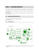
Part I. Getting Started RTL8812AU-CG module is a Miracast sink device, with Bluetooth Low Energy (BTLE) for easy connection. It can be installed to any device that requires a Miracast module for wireless display. The module uses a PIN-to-PIN connector to communicate with and obtain power supply from the host device. 1.1. Meeting RTL8812AU-CG This manual is applicable to the following catalog #s: RTL8812AU-CG 1.1.1.
1.2. System Requirements System requirements for the module are shown below: 1.2.1. Module Installation To install the module, the host device should provide a compatible PIN-to-PIN connector and an HD display. 1.2.2. Compatible Devices RTL8812AU-CG is compatible with the following devices: Wi-Fi Certified Miracast™ smartphones, tablets and notebook with Windows 10/8.
Part II. Installing the Dock 1. 2. 3. Connect RTL8812AU-CG module to the host device through the PIN-to-PIN connector. Power on the host device. Verify that the screen below is displayed on the host device’s display. The RTL8812AU-CG module is ready for use.
Part III. Connecting for the First Time This chapter explains how to connect RTL8812AU-CG for the first time to the source device. 3.1. Connecting using Miracast on Windows 10 Miracast is a peer-to-peer wireless screen display standard created by the Wi-Fi Alliance. It allows a portable device like a laptop or smartphone to wirelessly send up to 1080p HD video and 5.1 surround sound to a compatible display, like an HDTV.
Note: There are other ways to open the wireless display receiver list: Click the Start button, and then select Settings > Devices > Connected devices > Add a device to open the wireless display receiver list. Press the shortcut keys, Windows logo wireless display receiver list. 2. + K, on your keyboard to display the Press the shortcut keys, Windows logo + P, to open the Project menu, and then select Connect to a wireless display to open the wireless display receiver list.
3. Follow any instructions on the display device. You may be required to enter a PIN code. If a PIN is displayed on the connected display device, you should type this PIN in the PIN entry box and click Connect to continue.
4. The display device displays messages to show the status of the connection.
The device has connected to the dock. And the device’s screen is displayed on the HDTV. Note: Connection method on Windows 8.1 devices is similar. The path is Charm menu > Devices > Project > Add a wireless display. 5. 3.2. Connecting using Miracast on Android This section explains how to connect a Miracast™-enabled Android device, such as a smartphone, a tablet, or a game console, to the Receiver. For the best performance, the Miracast™ device should be running the latest software. 1.
device in the future. The next time the user walks into close range of the ScreenBeam Wireless Dock, BTLE beacons will be used to trigger the auto reconnect to the wireless device.
Part IV. Display and Control Options This chapter describes the display modes and control options that are supported by the Receiver. 4.1. Display Mode The Receiver supports three display modes when connected with a compatible wireless display application (Intel WiDi or Windows 8.1 Project, for example). In Windows, press the Windows logo + P keys simultaneously ( display options and select the desired display mode from the options.