
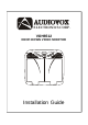
Installation Guide

-6-
VOH8512
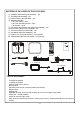
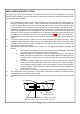
1) Insert the Circular Mini-Din Connector of the source Component Harness through the wire tie loop on
the main PCB and into the Nini-Din Connector on the main PCB.
2) Pull the wire tie loop tight and cut off the excess.
3) Connect the Power harness to the mating connector on the Video Monitor.
4) Connect power harness to vehicle’s electrical system by tapping into an accessory hot line and a
good ground.
5) Verify all functions of the System before final mounting of the finished assembly.
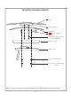
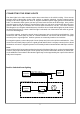
Red RCA (Audio Right)
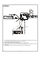
Clean the IR Receiver Window on the front of the VCP.
Remove Adhesive Backing and Apply IR LED to IR
White RCA (Audio Left)
"Y" Adapter
for use with
Non-Stereo
Installations
Power Connector
4 Pin
Accessory
Harness - Optional
(P/N:8010730)
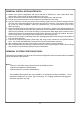
ANT. IN
RF OUT
VIDEO
125V 2A
+
-
TV
ANTENNA
To TV Antenna In
PODTVT
* ANTENNA FOR WIRELESS FM MOD
** See Antenna Note Below
SIRSWB
OPTIONAL
OPTIONAL
OPTIONAL
Dome Light
Power Source
CHOKE
Auxillary
video display
12 VDC Power
and Ground
INPUT
VIDEO
(Yellow)
Line Out-R (Red)
LINE
OUT
VIDEO
Patch Cord
RCA-Female
RCA Male to Male
Line Out-L (White)
Line Out-V (Yellow)
TO
OPTIONAL
ADDITIONAL
MONITOR
To Secondary AV Monitor
Power Harness
Item #3