
User Manual


www.acti.com
Hardware Manual
24
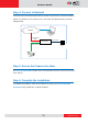
Loosen the screw and insert the wire through the pin slot, then tighten the screw to secure the
wire.
To connect digital input / output devices (DI/DO), map the pins to one of the pin combinations
below:
Device
Pin
Mapping Instructions
Digital Output
(DO)
12V
Connect the wires of the output device to 12V and
DO.
DO
Digital Input
(DI)
GND
Connect the wires of the input device to GND
and DI.
DI
The table below shows the DI/DO connection specifications:
Device
DI
Connection design
TTL - compatible logic levels
Voltage
To trigger (low)
Logic level 0: 0V ~ 0.4V
Normal (high)
Logic level 1: 3.1V ~ 30V
Current
10mA ~ 100mA
DO
Connection design
Transistor (Open Collector)
Voltage & Current
< 24V DC, < 50mA
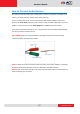
After mapping the wires to the terminal block, connect the terminal block to the DIO connector
of the camera.