IP Box Camera ACM-5711 Ver.
10 1.
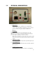
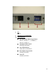
1.2 PHYSICAL DESCRIPTION 1. Ethernet Port The IP device connects to the Ethernet via a standard RJ45 connector. Supporting NWAY, this IP device can auto detect the speed of local network segment (10Base-T/100Base-TX Ethernet). 2. Reset Button Step 1: Switch off IP device by disconnecting the power cable Step 2: Press and continue to hold the Reset Button. Reconnect the power cable while continuing to hold the reset button.
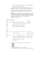
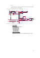
time lapse recording, alarm notifications, etc., the I/O terminal connector provides the interface to: •1 transistor output - For connecting external devices such as relays and LED:s. Connected devices can be activated by Output buttons on the Live View page or by an Event Type. The output will show as active (in Event Configuration > Port Status) if the alarm device is activated.
block. 2. Once the cables are connected, push the connector block into the terminal connector (also green) on the camera. 3.3V FUSE 1A 1 + DC TO DC 2 CONVERTER 3 - POWER INPUT EARTH GND GND DC POWER DI DI DO SW 1 RELAY 2 3 DIODE DEVICE 4 NPN DO CAMERA 6. Power Input If your power input is DC12V. 7. Analog Video Output The IP Box Camera supports one channel analog video output.
8. Iris DC Iris 9. Video DC Level Adjustment 10. CCD Functions z Auto Electronic Shutter Speed Mode AES On: 1/50 (60) sec. ~ 1/120,000 sec; AES Off: 1/50 (60) sec.
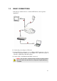
1.3 BASIC CONNECTIONS Follow the procedures below to connect the IP device to the respective apparatuses. 1. Connect the power adaptor to IP device 2. Connect IP device’s ethernet port to an Ethernet (RJ45 connectors). If your IP device has PoE built-in, you can regard it as a PD and connect it directly to a PSE device like PoE switch. 3. Connect a PC to the Ethernet hub (RJ45 connectors) 1 NOTE: You may find a support package for help you getting familiar with PoE.
21 Quick Tour This section guides you with a quick tour on this IP device. 2.1 Configure this IP Device 2.1.1 Make sure network environment Default IP of this IP device is 192.168.0.100. Please make sure this IP device and your PC are on the same network segment before running the installation. Please set the settings as below. IP address: 192.168. 0.xxx Subnet mask: 255.255.255. 0 (NOTE: xxx should be a number from 1 to 254, but 100 is excepted.
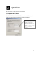
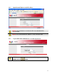
2.1.2 Open Internal Explorer with IP address NOTE: If your web browser is earlier than IE6, then download IE6 is recommended. NOTE: This IP device default IP address is set to 192.168.0.100 2.1.3 Login with default administrator’s account & password NOTE: Default administrator account is set to Admin, password is set to 123456, and click button.
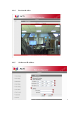
2.1.4 Preview the video 2.1.
*IP Address : The default IP address is 192.168.0.100. *Subnet Mask : The default subnet mask is 255.255.255.0 *Click button NOTE: In your Client PC, please make sure the setting of Network Connections Type is set to Auto Negotation, since this IP device follows MII standard. Otherwise, you might not see the live image. IMPORTANT: After the IP address is changed, please record this IP address. There’s no way to connect to the IP device if user forgets the new IP address. 2.1.