Megapixel IP Dome ACM-3401 Megapixel Day&Night IP Dome ACM-3411 Ver.
0 0 1. 2. 3. PRECAUTIONS Read these instructions All the safety and operating instructions should be read before the product is operated. Heed all warnings All warnings on the product and in the instruction manual should be adhered to. The symbol indicates the following items, please carefully read the description next to each symbol. a. Failure to follow the safety instruction given may directly endanger people, cause damage to the system or to other equipment. b.
and can radiate radio frequency energy and, if not installed and used in accordance with the instruction manual, may cause harmful interference to radio communications. Operation of this equipment in a residential area is likely to cause harmful interference in which case the user will be required to correct the interference at his own expense.
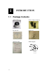
Table of Contents 0 PRECAUTIONS________________________________________________ 0-1 Trademarks ________________________________________________________________ 0-1 Liability ___________________________________________________________________ 0-1 FCC/CE Regulation __________________________________________________________ 0-1 1 INTRODUCTION ______________________________________________ 1-1 1.1 Package Contents _______________________________________________ 1-1 1.
11 1.
1.2 Features and Benefits This IP device is a cutting-edge digital video transmission device. It can compress and transmit real time images with outstanding images quality (SXGA, 1280x1024) at reasonable bandwidth through a standard TCP/IP network. That is because it is Ethernet ready and has the powerful ARM9 SoC with excellent system performance to offer dual streams of MPEG4/MJPEG, and both formats offer megapixel resolution.
detection delivers better sensitivity and responds faster than software motion detection. Bundle Powerful Surveillance Software To extend the capabilities of the IP outdoor rugged dome series, a powerful surveillance program is included in the package and is very free to use. Users can easily utilize the existing PC to be a digital video recorder. Schedule recording and manual recording keep every important image recorded in the local hard disk.
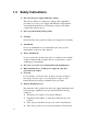
1.3 Safety Instructions Don’t use the power supply with other voltages This device is likely to be damaged or damage other equipments / personnel, if you use a power supply with different voltage than the one included with this device. All warranty of this product will be voided in the situations above. Don’t open the housing of the product Cleaning Disconnect this video product from the power supply before cleaning.
operating Instructions in this manual. Adjust only those controls that are covered by the instruction manual as an improper adjustment . Other controls may result in damage and will often require extensive work by a qualified technician to restore the video product to its normal operation. Safety Check Upon completion of any service or repairs to this video product, ask the service technician to perform safety checks to determine that the video product is in proper operating condition.
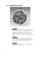
1.6 1-6 Physical Description 1. Reset Button Step 1: Switch off IP device by disconnecting the power cable Step 2: Press and continue to hold the Reset Button. Reconnect the power cable while continuing to hold the reset button. Step 3: Keep holding the reset button depressed for a while, release the reset button. The unit will start up with factory default settings. 2. Ethernet Port The IP device connects to the Ethernet via a standard RJ45 connector.
PIN 1 2 4. 1-7 NAME DESCRIPTION 12V DC Power Input GND Ground Pin Audio Input / Output The IP device supports audio input and output with terminal block.
1.5 Basic Connections Follow the procedures below to connect the IP device to the respective apparatuses. 1. Connect the power adaptor to IP device 2. Connect IP device’s ethernet port to an Ethernet (RJ45 connectors). If your IP device has PoE built-in, you can regard it as a PD and connect it directly to a PSE device like PoE switch. 3. Connect a PC to the Ethernet hub (RJ45 connectors) NOTE: You may find a support package for help you getting familiar with PoE.
1.6 1.6.1 Installation Procedure Ceiling Mount 1.6.1.1 Use the drill template, and drill a hole with φ35 on the ceiling 1.6.1.
1.6.1.3 Connect cables through the hole on the ceiling and plate, or on the side of casing 1.6.1.
1.6.1.5 Insert the cable(power/Network/audio) through the mounting plate and connect to the camera. Then use the little strap in bundled accessory to fasten the network cable. 1.6.1.
1.6.2 Wall Mount 1.6.2.1 Tighten wall mount bracket to the wall by 3 PAN Head Tapping screws 3-PAN HEAD SCREW TAPPING 1.6.2.
1.6.2.3 Note: that there’s a triangle mark on both plate and wall mount kit. Those triangle marks need to fix on the same direction. 1.6.2.4 Insert the cable(power/Network/audio) through the mounting plate and connect to the camera. Then use the little strap in bundled accessory to fasten the network cable.
1.6.2.5 Fasten the camera to wall mount kit by turning clockwise direction 1.6.2.
1.