
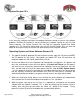
Instruction manual

System Documentation 040-1101-01 Rev C 5/19/2004 Page 23 of 27
Copyright © 2004, All Rights Reserved
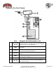
Computer Rear Panel Diagram
Port Computer Ports Description or Use
1
Video to ACT
LABS Gun
The Video Port on the computer connects first to the ACT
LABS Gun module. Use the Video Port on the ACT LABS Gun
Module to connect to the SVGA Monitor.
2 USB 0
USB Port 0 on the computer connects to the USB ACT LABS
Gun Module.
3 Parallel Port
The Parallel port connects to the Operator Buttons, and Coin
Door Mechs through the wiring harness
4 Audio Out
The Green Audio Out Port on the computer connect to the
speakers
5 USB 2
The USB Game Dongle connects to the USB Port 2 on the
lower part of the computer
6 AC Power
AC Power input must use a IEC 14 connector.
7 Video Out
The 15-pin video port connects to the Super VGA Monitor
cable inside the cabinet.