
User's Manual

SYSTEM DESCRIPTION AND INSTALLATION MANUAL
TCAS 3000 Traffic Alert and Collision Avoidance System
34−43−23
Use or disclosure of information on this page is subject to the restrictions in the proprietary notice of this document.
Page 2−2
15 Dec 2005
B. Antenna Provisions
The TCAS top directional antenna should, ideally, be the most forward antenna on the top
of the aircraft and should be located as close to the longitudinal centerline as possible.
See Figure 2−4. A 5−degree tilt angle is allowed laterally, with 2−degree positive and
5−degree negative tilt angles allowed longitudinally. See Figure 2−5.
If a bottom directional antenna is used, it should also be the most forward antenna on the
fuselage bottom. Tilt angle allowances are the same as on the top antenna. A bottom
omnidirectional antenna need not be the most forward antenna, but it should be
separated by at least 20−inches from any other L−band antenna.
Since the bottom antenna may be either a directional (standard) or an omnidirectional
(optional) antenna, dual notation is shown in the wiring diagram. Only one coax cable is
needed for an omnidirectional antenna installation.
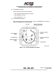
(1) Directional Antenna Installation
The top directional antenna mounting and installation data is given in Figure 2−6.
Figure 2−6 contains the maximum radius dimensions for the various curved antenna
base part number units, the number of aircraft mounting holes and the length of the
connector extension for the various part number units. The antenna must be
electrically bonded (less than 5.0 milliohms bonding resistance) to the airframe to
provide a good ground contact for lightning protection.
The directional antenna must be separated by a least 30−inches from any other
L−band antenna, and 60−inches is preferred. If a bottom directional antenna is used,
it should be the most forward antenna on the fuselage bottom with tilt angle
allowances the same as for a top mounted antenna.
An O−ring (included with the directional antenna) is required to be installed between
the directional antenna and the aircraft fuselage. The Navy Aeronautical Standard
part number for the O−ring is NAS 1611−240. The ACSS part number for the O−ring
is 4000171−240.
NOTE: For directional antennas, ACSS Part No. 7514060−90X, the customer must
provide an adapter plate for mounting to the aircraft. The antenna base
plate, to which the adapter must mate, is detailed in Figure 2−7. Directional
antennas, ACSS Part No. 7514081−9XX, come with a preinstalled adapter
plate.
(2) Omnidirectional Antenna Installation
The bottom omnidirectional antenna is a standard ATC type antenna. It should be
qualified to TSO C119a and be dc grounded per MIL−A−90941, B−5087B. All
L−band antennas must be separated by at least 20−inches. Only one coax cable is
required for installation.
The omnidirectional antenna is not supplied by ACSS. To install, follow the
manufacturer’s installation instructions.