
User's Manual

SYSTEM DESCRIPTION AND INSTALLATION MANUAL
TCAS 3000 Traffic Alert and Collision Avoidance System
34−43−23
Use or disclosure of information on this page is subject to the restrictions in the proprietary notice of this document.
Page 2−1
15 Dec 2005
MECHANICAL INSTALLATION
1. General
This section contains information on how and where to mount each component of the TCAS
3000 system. For new installations, plan installation in two stages. First, determine location
of the LRUs in the aircraft. Next, determine the length of RF and electrical interconnections
for selected locations.
NOTE: The TCAS 3000 LRU, ACSS Part No. 9003000−10XXX can functionally replace a
TCAS 2000 LRU, Part No. 4066010−904, −905, or −907, in existing installations.
Certification approval must be obtained.
TCAS 2000 LRUs, Part No. 4066010−904, −905, −907, −910, or 7517900−10XXX
may replace the TCAS 3000 if properly demonstrated and certified.
2. Equipment and Materials
For new TCAS 3000 installations, refer to Table 1−1 for RCZ−852 Transponder Installation Kit
information and Table 1−2 for mounting tray information. For all other components, refer to
the applicable Outline and Installation drawing in this section for mounting information. The
Outline and Installation drawings show connector and connector contact pin/socket part
number information, where applicable.
3. Mechanical Installation Design
NOTE: To assure proper grounding of the TCAS 3000 system, the aircraft surface to which
all mountings or units are attached must be clean bare metal. Mount to the airframe
with a resistance of 5 milliohms or less.
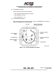
A. TCAS 3000 Computer Unit Provisions
Mechanical installation data for the TCAS 3000 Computer Unit (6−MCU) is shown in
Figure 2−1. Data for the TCAS 3000 Computer Unit (4−MCU) is shown in Figure 2−2.
The computer unit can be mounted in any convenient location in the aircraft; however, it
must be located so as to maintain an antenna coaxial cable insertion loss of 2.5 ± 0.5 dB
in accordance with DO−185. This is approximately within 50 feet of the antenna unless
low loss coaxial cable is used. Top and bottom coaxial delay timing differences can be
compensated for by use of the antenna delay program pins.
The TCAS Computer Unit, Part No. 9003000−10XXX, is mounted in an ARINC 600
6−MCU mounting tray. The computer unit requires external cooling air in accordance with
ARINC 600 or ARINC 404 to maintain the highest possible Mean Time Between Failures
(MTBF). In those installations where this is not available, a mounting tray with an integral
fan is required.
The TCAS Computer Unit, Part No. 9003000−55XXX or 65XXX, is mounted in an ARINC
600 4−MCU mounting tray. This unit contains an internal temperature controlled fan, so it
does not require any external cooling.