
User's Manual

SYSTEM DESCRIPTION AND INSTALLATION MANUAL
TCAS 3000 Traffic Alert and Collision Avoidance System
34−43−23
Use or disclosure of information on this page is subject to the restrictions in the proprietary notice of this document.
Page 1−29
15 Dec 2005
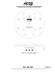
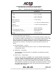
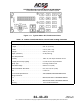
Table 1−7. ACSS Control Panel Leading Particulars
Item Specification
Dimensions (maximum):
• Height . . . . . . . . . . . . . . . . . . . . . . . . . . . . . . . . . . . . . . . 2.25 in. (57.2 mm)
• Width . . . . . . . . . . . . . . . . . . . . . . . . . . . . . . . . . . . . . . . . 5.75 in. (146.1 mm)
• Length . . . . . . . . . . . . . . . . . . . . . . . . . . . . . . . . . . . . . . . 5.00 in. (127.0 mm)
Weight (maximum) . . . . . . . . . . . . . . . . . . . . . . . . . . . . . . 2.1 lb (0.953 kg)
Power Requirements:
• Primary . . . . . . . . . . . . . . . . . . . . . . . . . . . . . . . . . . . . . . 115 V, 400 Hz (2.0 Watts maximum)
• Lighting . . . . . . . . . . . . . . . . . . . . . . . . . . . . . . . . . . . . . . 5 V, 400 Hz (3.0 Watts maximum)
Mating Connectors:
• J1 . . . . . . . . . . . . . . . . . . . . . . . . . . . . . . . . . . . . . . . . . . . M83723/75R1624S7
• J2 (Dual Mode S Version) . . . . . . . . . . . . . . . . . . . . . . M83723/75R1624S8
• J2 (ATCRBS/Mode S Version) . . . . . . . . . . . . . . . . . . MS3476L2041S
Mounting . . . . . . . . . . . . . . . . . . . . . . . . . . . . . . . . . . . . . . . Unit Dzus Fasteners
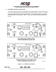
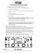
(1) Functional Description and Operation
Communication with Mode S transponders is accomplished through an ARINC 429
bus as defined in ARINC Characteristic 718−A. Control panel functions include 4096
ident code selection and display, altitude source and reporting inhibit selection,
selection between two onboard transponders, TCAS TA or TA/RA advisory selection,
and selection of TCAS test. A listing of the control panel switch functions is as
follows:
(a) ALT RPGT Switch − 1, OFF, 2
Used to select between altitude sources 1 and 2, or to disable altitude reporting
in transponder replies.
(b) XPDR FAIL − Annunciator
The illumination of the annunciator is an indication of a performance monitor
failure detection.
(c) Mode Control − Rotary Switch
Disables reply capability in STANDBY mode. Enables MODE S transponder in
ON mode. Enables ATCRBS transponder in ATC mode. The TA mode enables
the TCAS computer, in conjunction with the Mode S transponder, to provide
traffic advisories. The TA/RA mode enables the TCAS computer, in conjunction
with the Mode S transponder, to provide traffic and resolution advisories. The TA
and TA/RA modes are electrically tied to the ON mode and enable the Mode S
transponder when selected.