
User's Manual

SYSTEM DESCRIPTION AND INSTALLATION MANUAL
TCAS 3000 Traffic Alert and Collision Avoidance System
34−43−23
Use or disclosure of information on this page is subject to the restrictions in the proprietary notice of this document.
Page 1−25
15 Dec 2005
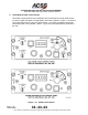
When less than 10 flight legs have been flown since the TCAS Computer Unit was
shop tested and recertified, less than 10 previous flight legs of recorded fault data
may be available for display. In this case, if an attempt is made to display fault data
for the preceding flight leg when the earliest flight leg is displayed, all annunciators
flash for 3 seconds at a 2.5−Hz rate and then all annunciators are extinguished.
The TCAS PASS and TCAS FAIL annunciators indicate the status of the TCAS
Computer Unit only. All other annunciators reflect the condition of the respective
sub−system. During troubleshooting, the TCAS Computer should not
be removed if
the TCAS PASS lamp is on.
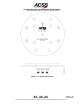
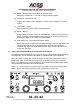
B. Directional Antenna
The TCAS directional antenna, Figure 1−9, is a four−element, vertically polarized,
monopole array capable of transmitting in four selectable directions at 1030 MHz. The
antenna is capable of receiving replies from all directions simultaneously with bearing
information at 1090 MHz, using amplitude−ratio monopulse techniques.
The antenna consists of a molded radome with radiating/receiving elements and is
completely filled with a rigid foam. The antenna assembly uses five or nine screws to
attach the radome and either four or eight screws to attach the antenna to the aircraft
fuselage.
The ACSS directional antenna has a small frontal area. The circular radome has a 3:1
elliptical leading edge and an extremely low profile height of only 0.806 inch. This yields
excellent aerodynamic performance with a minimum possibility of icing, which could be a
hazard for rear mounted engines.
For TCAS 3000 system installations, the top antenna must be a directional antenna. The
bottom antenna can be either a directional or omnidirectional antenna. The TCAS
Computer Unit has the capability of automatically sensing which version is installed.
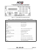
The directional antenna mounting screws (not included with the directional antenna) are
standard #10−32 UNF−2A pan head, corrosion−resistant (stainless) steel screws in
accordance with Military Specification MS51958. The appropriate length is determined by
the installer allowing 0.5−inch for the thickness of the antenna and adapter plate. A
washer must be installed under the head of each mounting screw. The washer must be
made of passivated, corrosion−resistant steel in accordance with MIL−S−5059 or
MIL−S−6721. The Air Force−Navy Aeronautical Standard part number is AN960C10L.
The washer has an outer diameter of 0.438 inch, an inner diameter of 0.203 inch, and a
thickness of 0.032 inch.