
User's Manual


SYSTEM DESCRIPTION AND INSTALLATION MANUAL
TCAS 3000 Traffic Alert and Collision Avoidance System
34−43−23
Use or disclosure of information on this page is subject to the restrictions in the proprietary notice of this document.
Page 1−22
15 Dec 2005
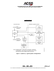
(d) Data Loader Interface
The TCAS 3000 computer contains a set of ARINC 429 busses and discrete
inputs that interface to either an airborne data loader (ADL) through pins on the
rear connector, or a portable data loader (PDL) through the 53−pin circular
connector on the front panel of the unit. The computer works with ARINC 615
data loader protocol (high speed bus). The unit software part number can be
output on the data loader port by grounding a discrete input.
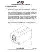
(e) RS−232 / Compact Flash Card Data Recorder Interface
The Data Recorder Interface can be utilized for either internal or external data
recording.
The TAWS/RWS event log contains event information due to TAWS or windshear
cautions or warnings (internal data recording). The log can hold approximately
three events that last up to 45 seconds each (assuming GCAM Event, GCAM
parameter data, and GFM parameter data selected for recording). The event
log data may be downloaded to a Laptop PC over the RS−232 port, or
downloaded to a Compact Flash card using the slot on the front of the unit.
The external data recording provides the capability to perform real−time
recording of various T
2
CAS input, output, and internal data. This data may be
recorded using the Compact Flash card or RS−232 interface.
In addition, the RS−232 interface allows for LRU maintenance and
troubleshooting. The maintenance log and RA event log can also be
downloaded to a PC using this port. The RS−232 interface is connected to the
53−pin PDL connector on the front of the unit.
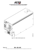
(f) TCAS Display Bus interface
The TCAS 3000 computer has four sets of ARINC output busses for display of
traffic and resolution advisories.
The TA/RA Display No. 1 and No. 2 busses are high speed ARINC 429 busses
that contain both traffic information and resolution advisory information. The
busses function according to either the ARINC 735 characteristics, or can
optionally be set for the Honeywell EFIS characteristics through a program input
pin (RMP−12C). For each bus, a valid discrete input is provided that indicates
whether the display is functional.
The RA Display No. 1 and No. 2 busses are low speed ARINC 429 busses that
contain only resolution advisory information. The busses function according to
the ARINC 735 characteristics. For each bus, a valid discrete is provided that
indicates whether the display is functional.
The RA Display No. 1 and No. 2 busses can be configured for a 429 Data
Recorder function by grounding programming pin (RMP−11D). In this mode, the
busses are configured for high speed operation.