
User's Manual

SYSTEM DESCRIPTION AND INSTALLATION MANUAL
TCAS 3000 Traffic Alert and Collision Avoidance System
34−43−23
Use or disclosure of information on this page is subject to the restrictions in the proprietary notice of this document.
Page 1−9
15 Dec 2005
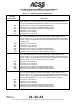
GROUND
STATION
AD−53001@
TCAS
CU
MODE S
XPDR
MODE S
XPDR
TCAS
CU
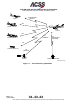
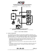
Figure 1−2. TCAS/Mode S Communication
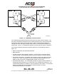
The TCAS 3000 generates both RAs and TAs when the TA/RA mode is selected. The
two types of advisories correspond to time−based protection zones around the aircraft.
The airspace around the TCAS aircraft where an RA is annunciated represents the
warning area, while the larger airspace which results in a TA being annunciated is the
caution area. Figure 1−3 contrasts the airspace covered by the two types of advisories.
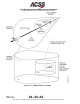
The onboard equipment listed below must be linked to the TCAS 3000 as shown in
Figure 1−4.
• Mode S transponder with associated antennas
• Radio altimeter
• Air Data Computer (ADC) (digital or analog). If an ADC does not support vertical
speed rate data, an optional PTM must be used if the display is a ACSS VSI/TRA.
• ATC/TCAS control panel. A separate control panel is not the only method of control
for the TCAS. Other components, such as a Honeywell Radio Management Unit
(RMU) as part of a Primus II Integrated Radio System, can be used.
• Omnidirectional antenna. The TCAS 3000 accepts two types of bottom antennas: A
standard directional antenna or an optional ATC−type omnidirectional antenna. If an
omnidirectional antenna is installed, it must be supplied by the installer. If a directional
antenna is installed at both top and bottom antenna locations, a bottom
omnidirectional antenna is not needed.