
User's Manual

SYSTEM DESCRIPTION AND INSTALLATION MANUAL
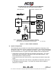
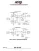
TCAS 3000 Traffic Alert and Collision Avoidance System
34−43−23
Use or disclosure of information on this page is subject to the restrictions in the proprietary notice of this document.
Page 1−3
15 Dec 2005
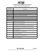
Table 1−2. System Components Not Supplied by ACSS
Component Comments
Gables G7130 Series ATC/TCAS Dual Transponder Control
Panel (Note 1.)
General aviation type controller that
operates from 28 V dc aircraft power
(Note 2.)
Gables G6990, G6991, G6992, G6993, and 7490 Series
Mode S/TCAS Control Panels (Note 1.)
Commercial aviation type controllers
that operate from 115 V ac aircraft
power (Note 2.)
Omnidirectional TCAS Antenna (Note 3.) ATC blade antenna, dc shorted, TSO
C119a compliant,1030 to 1090 MHz.
Installer to supply antenna.
Omnidirectional ATC Antennas (Note 4.) ATC blade antenna, dc shorted, TSO
C112 compliant, 1030 to 1090 MHz.
Installer to supply antenna.
Mounting Tray, TCAS Computer (6−MCU size unit) ARINC 600 6−MCU Mount, cooling air
required. Installer to supply mount.
Mounting Tray, TCAS Computer (4−MCU size unit) ARINC 600 4−MCU Mount, no cooling
air required. Installer to supply mount.
Mounting Tray, Data Link Transponder (4−MCU size unit) ARINC 600 4−MCU Mount, cooling air
recommended but not required.
Installer to supply mount.
NOTES:
1. Refer to Table 1−4 for individual part number descriptions.
2. For additional information, pricing and availability contact:
Gables Engineering, Inc. 247 Greco Avenue, Coral Gables, Florida 33146
Telephone (305) 774−4400
Fax (305) 774−4465
3. A bottom omnidirectional antenna can be used as an optional replacement for the directional
antenna.
4. A diversity transponder installation requires both a top and bottom ATC antenna.
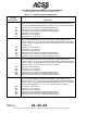
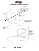
Table 1−3. Directional Antenna Configurations
Antenna
Part Number
Description
7514081−901 Directional antenna with flat base, four hole mounting pattern, and 1.560−inch
connector extension length
7514081−902 Directional antenna with flat base, eight hole mounting pattern, and 1.560−inch
connector extension length
7514081−903 Directional antenna with a curved 61.52−inch radius base, eight hole mounting
pattern, and 1.560−inch connector extension length
7514081−904 Directional antenna with a curved 66.52−inch radius base, eight hole mounting
pattern, and 1.560−inch connector extension length