
User's Manual

SYSTEM DESCRIPTION AND INSTALLATION MANUAL
TCAS 3000 Traffic Alert and Collision Avoidance System
34−43−23
Use or disclosure of information on this page is subject to the restrictions in the proprietary notice of this document.
Page 6−19
15 Dec 2005
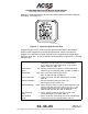
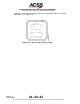
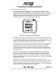
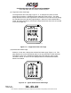
(11) Option Pins Status Page
Selection of code 0012 displays a page that defines the TCAS computer option pins.
See Figure 6−13.
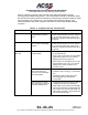
Figure 6−13. Typical Option Pins Status Page
Option pins on the TCAS computer associated with each of the functions defined on
the Option Pins Status page are listed below. Where more than one option pin is
indicated, the listed connector pins correspond to the display digits read from left to
right.
There are eight option pins available on the TCAS computer for selection of various
options. The OPT PINS are as follows: RMP−10G, −10H, −10J, −10K, −11A, −11B,
−11C, and −11D.
NOTE: OPT PINS RMP−10G, −10H, −10J, and −10K are reserved for future
enhancements and are used for parity check only.
The PARITY line (line 4) displays the status of the parity program pin (RMP−12G).
Pin RMP−12G must be grounded (1) when the number of OPT PINS grounded is an
odd number (1, 3, 5, 7). If number of OPT PINS grounded is an even number (0, 2,
4, 6, 8), then pin RMP−12G should be open (0).
The STATUS line (line 5) displays FAIL if the option pins parity is incorrect or PASS if
parity is correct.
The ENHANCEMENTS line (line 6) displays the status of the Flight Data Recorder
ARINC 429 and Extended Maintenance Log Program input status (Pin RMP−11D).
This option enables the use of the Flight Data Recorder and the down loading of the
extended maintenance log through a PDL connected to connector J1 located on the
front of the TCAS computer. If pin RMP−11D is open, the Flight Data Recorder is not
used and normal RA display bus operation occurs. If pin RMP−11D is grounded,
high speed ARINC 429 flight data is output on the RA Display #1 and #2 busses and
maintenance log data can be downloaded through a portable data loader.