
User's Manual

SYSTEM DESCRIPTION AND INSTALLATION MANUAL
TCAS 3000 Traffic Alert and Collision Avoidance System
34−43−23
Use or disclosure of information on this page is subject to the restrictions in the proprietary notice of this document.
Page 5−2
15 Dec 2005
C. LRU Preinstallation Power Checkout
Before you do any operational tests, a power−on check is recommended to reduce the
possibility of damage to newly installed system components due to miswired power leads.
(1) Make sure all TCAS system components are removed from their mounting trays or
that their aircraft mating connector(s) are disconnected.
(2) Connect external power to aircraft.
(3) Close all TCAS system 115 V, 400 Hz circuit breakers, if applicable, and check for
115 V ac at the appropriate LRU mating connector pins. Refer to the applicable
interconnect diagrams for LRU pin numbers.
(4) Close all TCAS system 28 V dc circuit breakers, if applicable, and check for 28 V dc
at the appropriate LRU mating connector pins. Refer to the applicable interconnect
diagrams for LRU pin numbers.
(5) If power is misapplied on any connector pin, open the circuit breaker and rework
miswired harness.
(6) Remove aircraft power.
D. Initial System Installation Operational Test
The initial checkout of a newly installed system should start with a system self−test and
then be followed by a ramp test. The system self−test procedures are referenced in
paragraph 4.A. The ramp tests should include a Scenario Test and a Power and
Frequency Test. Refer to the applicable TCAS Ramp Tester Operation Manual for
procedures to do these tests.
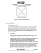
If a ACSS VSI/TRA is used as the display instrument, it contains a feature that displays
some typical installation errors. See Figure 5−1. If an error is detected during initial
installation checkout, the VSI/TRA displays the error as follows:
(1) Removes all symbology from the display
(2) Displays a red X that covers the entire screen
(3) Displays a two digit error code as follows:
• 00 = Invalid discrete setting at power−up
• 01 = Invalid light curve setting specified at power−up
• 03 = Bad checksum detected at power−up
• 04 = Illegal op−code test failed
• 05 = Unsupported test failed.
(4) Strobes the watchdog timer to keep the red X and status displayed.
NOTE: If the VSI/TRA displays error code 10, 11, 12, 29, 30, 31, or 40 an internal
VSI/TRA failure has been detected.