
User's Manual


SYSTEM DESCRIPTION AND INSTALLATION MANUAL
TCAS 3000 Traffic Alert and Collision Avoidance System
34−43−23
Use or disclosure of information on this page is subject to the restrictions in the proprietary notice of this document.
Page 4−30
15 Dec 2005
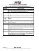
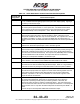
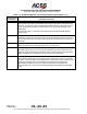
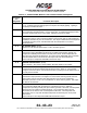
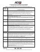
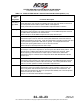
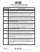
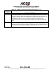
Table 4−4. Gables Control Panel Interface Descriptions (cont)
Connector Pin
Designation
Functional Description
J1/J2−22, 23 ARINC 429 OUTPUTS: (J1/J2−22,23)
Communication between the control panel and the transponder is done over a two wire
low speed, odd parity, ARINC 429 compatible bus. Selected ATC code, operating mode,
and system parameters are communicated to the transponder over these lines.
Transmission of labels 013, 015, 016, and 031 is done every 150 milliseconds.
Connect these pins to one of the two transponder ARINC 429 CONTROL DATA Input
Ports.
J1/J2−24 AIR/GROUND INPUT DISCRETE: (J1/J2−24)
The control panel accepts input from two independent Air/Ground (WOW) switches for
applications that require automatic disabling of the transponder upon landing. This input
is wired directly to the AIR/GROUND SW Discrete Output (J1/J2−15).