
User's Manual


SYSTEM DESCRIPTION AND INSTALLATION MANUAL
TCAS 3000 Traffic Alert and Collision Avoidance System
34−43−23
Use or disclosure of information on this page is subject to the restrictions in the proprietary notice of this document.
Page 4−27
15 Dec 2005
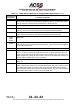
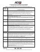
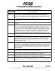
Table 4−3. ACSS ATCRBS−Mode S Control Panel Interface Descriptions (cont)
Connector
Pin
Designation
Functional Description
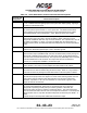
J2−X, Y, Z, a,
b, c, d, e, f,
g, h and i
MODE A REPLY CODE PULSE OUTPUTS:
These 4096 Reply Code outputs are manually set by the reply code knobs on the front of
the control panel and are used for replies to Mode A interrogations.
These pins should be connected to the ATCRBS transponder Mode A interface.
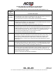
J2−j IDENT OUTPUT: (J2−j)
This discrete output provides a low signal (Ground) to an ATCRBS transponder whenever
the IDENT button is pushed on the Control Panel.
Connect this pin to the ATCRBS transponder Ident (SPI) discrete input.
J2−m ATC FAIL INPUT: (J2−m)
This discrete input is used to control the control panel XPDR FAIL annunciator when an
ATCRBS transponder is being used. When the transponder is operating normally, this input
is open (resistance greater than 100K ohms to ground). If a transponder failure has
occurred, this input is greater than 4.0 V dc at 100 mA of current.
Connect this pin to the transponder ATC FAIL output.
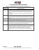
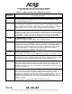
J2−r ALTITUDE REPORTING ON OUTPUT: (J2−r)
Ground/Open output that is dependent on the front panel ALT RPTG switch position. This
discrete output is enabled when altitude reporting is selected in the ON mode. When
altitude reporting is selected OFF, the output at pin J2−r will be in the OPEN state.
This discrete output is connected to the transponder ALTITUDE REPORTING ON/OFF
Discrete Input.
J2−s TEST OUTPUT: (J2−s)
This discrete output provides a low signal (Ground) to an ATCRBS transponder whenever
the TCAS TEST button is pushed on the Control Panel. The control panel Mode switch
must be in the ATC position to initiate an ATCRBS transponder test.
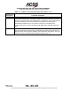
J2−t TRANSPONDER NO. 1 ON: (J2−t)
This discrete output puts a Mode S transponder in either a standby or active mode. It is
used in conjunction with the Mode switch on the front panel of the Control Panel. The
output uses Ground/Open logic where an Open specifies Standby and a Ground specifies
an Active mode (ON, TA, or TA/RA).
This pin is not used with ACSS Mode S Transponders.