
User's Manual


SYSTEM DESCRIPTION AND INSTALLATION MANUAL
TCAS 3000 Traffic Alert and Collision Avoidance System
34−43−23
Use or disclosure of information on this page is subject to the restrictions in the proprietary notice of this document.
Page 4−23
15 Dec 2005
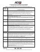
Table 4−2. ACSS Dual Mode S Control Panel Interface Descriptions
Connector Pin
Designation
Functional Description
J1−1,2 PANEL AND DISPLAY LIGHTING INPUT: (J1−1 LOW, J1−2 HIGH)
5 V ac, 3.0 Watts maximum lighting input for front panel and display lighting. Lighting is
provided by incandescent lamps.
J1/J2−3,4 115 V ac INPUT POWER: (J1/J2−3 HIGH, J1/J2−4 LOW)
The control panel is powered from a 115 V ac power bus. Two identical but isolated
power supplies provide the power requirements to each individual electronic module
which independently control, transponder 1 and 2. Maximum power is 2.0 Watts.
J1/J2−5 ANTENNA TRANSFER DISCRETE OUTPUT: (J1/J2−5)
These discrete outputs are used to provide the ability to switch a RF relay for dual
transponder installations that have only one set of antennas. The outputs from J1 and J2
are linked to the XPDR 1−2 switch. The output is OPEN when the transponder is in
standby (inactive) mode, and GROUND when the transponder is in an active operational
mode.
J1/J2−6 DC GROUND INPUT: (J1/J2−6)
Reference for all discrete inputs/outputs. Tied to aircraft dc ground.
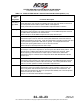
J1/J2−7 STANDBY/ON OUTPUT: (J1/J2−7)
These discrete outputs (STANDBY/ON) will mimic the XPDR switch position placing one
transponder in Standby and the other in the ON (active) mode. Both transponders will
never be in the ON mode simultaneously. This output is low (GROUND) when in Standby
mode and OPEN when in the ON mode. This output can sink 100 mA maximum.
Connect pin to transponder STANDBY / ON Discrete Input.
J1/J2−8 CHASSIS GROUND INPUT: (J1/J2−8)
Tied to airframe. Also used to connect ARINC 429 cable shields to the chassis.
J1−9 FUNCTIONAL TEST INPUT: (J1−9)
Functional test can also be initiated using this discrete input. When J1−9 is grounded, a
functional test similar to pushing the TCAS TEST button on the front panel is initiated.
J1−10 WARNING AND CAUTION OUTPUT: (J1−10)
This discrete output provides a low signal to a remote master warning system when the
control panel receives a Monitor Lamp fault indication from the active transponder.
Otherwise, it provides 7 to 30 V dc or a resistance of >100 K Ohms to ground. This
output can sink 20 mA maximum.
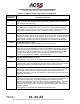
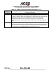
J1/J2−12 XPDR FAIL #2 INPUT: (J1/J2−12)
The control panel XPDR FAIL annunciator is controlled by this input. When the
transponder is operating normally this input remains grounded. Otherwise, the
transponder opens this input to indicate a transponder failure. The control panel then
turns the annunciator ON to alert the user of a transponder malfunction. The transponder
fail annunciator turns on only when the failed transponder is selected by the XPDR 1−2
switch.
Connect this pin to the transponder XPDR FAIL #2 Discrete Output.