
User's Manual


SYSTEM DESCRIPTION AND INSTALLATION MANUAL
TCAS 3000 Traffic Alert and Collision Avoidance System
34−43−23
Use or disclosure of information on this page is subject to the restrictions in the proprietary notice of this document.
Page 4−22
15 Dec 2005
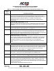
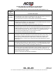
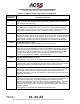
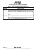
Table 4−1. TCAS 3000 Computer Unit Loading/Gradient Specifications (cont)
Connector Pin
Designation
Functional Description
J1−37, 38 28 V dc Power Output: [J1−37 (HI), J1−38 (LO)]
These power output pins provide the 28 V dc operating power for the data loader. These
pins are used only if the data loader operates from a +28 V dc source.
J1−39 Reserved
J1−40 RS−232 Data Input
This pin is used to receive RS−232 data from a portable maintenance terminal.
J1−41 RS−232 Data Output
This pin is used to transmit RS−232 data to a portable maintenance terminal.
J1−42
Thru
J1−47
Spare Pins
J1−48,
J1−49
Logic Common
Common lines for the RS−232 Data Input/Output lines. These two pins are tied together
in the TCAS computer unit.
J1−50 Reserved Pin
J1−51 Data Loader Link No. 2 Discrete Input
Pins J1−51 and J1−52 are ground/open discretes from a portable data loader, which are
used to specify what type of data loader (ARINC 603 or ARINC 615) is connected to the
TCAS computer unit. These two pins are also connected to the ARINC 600 connector on
the rear of the unit (RBP−6B and −6C respectively).
J1−52 Data Loader Link No. 3 Discrete Input
See J1−51.
J1−53 Data Loader Link No. 4 Discrete Input
This is a ground/open discrete from a Portable Data Loader (PDL) that is used to transmit
the software part number on the Data Loader output bus when grounded, The landing
gear indicates extended, and the air/ground indicates ground. This pin is also connected
to the ARINC 600 connector on the rear of the unit (RBP−6D).