
User's Manual

SYSTEM DESCRIPTION AND INSTALLATION MANUAL
TCAS 3000 Traffic Alert and Collision Avoidance System
34−43−23
Use or disclosure of information on this page is subject to the restrictions in the proprietary notice of this document.
Page 4−21
15 Dec 2005
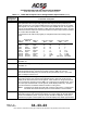
Table 4−1. TCAS 3000 Computer Unit Loading/Gradient Specifications (cont)
Connector Pin
Designation
Functional Description
J1−8, 9 ARINC 429 Data Loader/PDL Recorder Bus Output: [J1−8 (A), J1−9 (B)]
This differential pair output is a high−speed ARINC 429 bus (100K bits/second nominal)
that is used to output data from the TCAS computer unit to the data loader. The
standards for this interface are defined in ARINC 615 Airborne Computer High Speed
Data Loader.
These pins should be connected to pins 8 and 9 of the PDL cable interface.
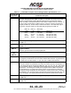
J1−10
thru
J1−15
ARINC 615 Data Loader
Reserved
J1−16 Input Bus Shields
The shields from the input bus (J1−1, 2) should be connected to this pin.
J1−17 Spare Pin
J1−18 PDL Link A Discrete Input
This is a ground/open discrete from an portable ARINC 615 or ARINC 603 data loader
which indicates, to the TCAS computer unit, that a data loader is connected. A ground
indicates a data loader is connected.
J1−19 PDL Link B Common
Connect this pin to pin 19 of the PDL cable interface.
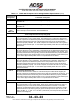
J1−20, 22 115 V ac Power Output: [J1−20 (H), J1−22 (C)]
These power output pins provide the 115 V ac operating power for the data loader.
The 115 V ac (H) and 115 V ac (C) interconnect wires should be shielded or twisted and
shielded with an insulating jacket over the shield. The shield should be connected to
chassis ground (J1−21).
J1−21 Chassis Ground
Connect 115 V ac power shields to this pin.
J1−23 ARINC 615 Data Loader Ethernet Input (RD+)
J1−24
thru
J1−32
Reserved
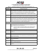
J1−33,34 ARINC 429 TA/RA Display No. 1 Output: [J1−33 (A), J1−34 (B)]
This bus can be used to connect to a maintenance display. These pins are also
connected to the ARINC 600 connector on the rear of the unit (RMP−7C and −7D).
J1−35,
J1−36
Reserved