
User's Manual

SYSTEM DESCRIPTION AND INSTALLATION MANUAL
TCAS 3000 Traffic Alert and Collision Avoidance System
34−43−23
Use or disclosure of information on this page is subject to the restrictions in the proprietary notice of this document.
Page 3−50
15 Dec 2005
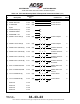
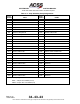
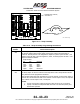
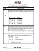
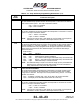
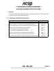
Table 3−8. RCZ−852 Diversity Mode S Transponder Interconnect Data (cont)
I/O NotesConnects To
Connector
Pin
Description
(I) dc GROUND J1−19 (22) Acft dc Ground
(I) XPDR +28V RTN J1−20 (22) Acft dc Ground
(I) dc GROUND J1−21 (22) Acft dc Ground
Spare J1−22
(O) XPDR VALID (PO) J1−23 NC
(I) XPDR RX RS232 J1−24 NC
(O) PROGRAM +15V J1−25 NC
(O) XPDR to TCAS 429 (A) J1−26 (22) S T S
GND
ll
GND
||
TCAS Computer 2
(O) XPDR to TCAS 429 (B) J1−27 (22) S T S
GND
ll
GND
TCAS Computer 2
(O) XPDR to DLP A/B 429 (A) J1−28 (22) S T S
||
Airborne Data Link
Processor
2
(O) XPDR to DLP A/B 429 (B) J1−29 (22) S T S
GND
ll
GND
Airborne Data Link
Processor
2
(O) XPDR to DLP C/D 429 (A) J1−30 (22) S T S
||
Airborne Data Link
Processor
2
(O) XPDR to DLP C/D 429 (B) J1−31 (22) S T S
GND
ll
GND
Airborne Data Link
Processor
2
(I) ADC1 to XPDR 429/575A J1−32 (22) S T S
||
ARINC 429 or 575
ADC #1
2
(I) ADC1 to XPDR 429/575B J1−33 (22) S T S
GND
ll
GND
ARINC 429 or 575
ADC #1
2
(I) CTL1 to XPDR 429 (A) J1−34 (22) S T S
||
Control Panel 2
(I) CTL1 to XPDR 429 (B) J1−35 (22) S T S
GND
ll
GND
Control Panel 2
Reserved J1−36
Reserved J1−37
Reserved J1−38
Reserved J1−39