
User's Manual

SYSTEM DESCRIPTION AND INSTALLATION MANUAL
TCAS 3000 Traffic Alert and Collision Avoidance System
34−43−23
Use or disclosure of information on this page is subject to the restrictions in the proprietary notice of this document.
Page 3−49
15 Dec 2005
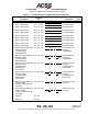
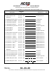
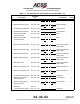
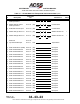
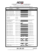
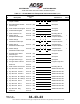
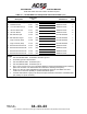
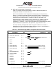
(2) RCZ−852 Diversity Mode S Transponder
Table 3−8 contains the interconnect data for the RCZ−852 Diversity Mode S
Transponder, Part No. 7510700−850/−951.
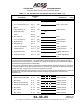
Prior to final installation of the transponder mounting tray, the strap assembly,
Figure 3−12, located on the back of each mounting tray must be programmed to
incorporate the aircraft Mode S address and the desired options. Information for
programming the strap assembly is contained in Table 3−9 and Table 3−10.
Programming of the strap assembly consists of removing or installing a string of
jumper wires that provide a 48−bit serial data word for encoding the system
configuration. In Table 3−10, the output is grounded if the corresponding W* (jumper
wire) is installed for a particular bit, and open if the jumper wire is cut out.
The strap assembly is shipped with all 48−bit jumpers installed. If a jumper is
inadvertently cut out or a parameter change requires a jumper to be reinstalled, a
suitable piece of AWG 24 bus wire should be used.
Table 3−8. RCZ−852 Diversity Mode S Transponder Interconnect Data
I/O Description
Connector
Pin
Connects To Notes
(O) XPDR +28 V FAN RTN J1−1 NC
(O) XPDR +28 V FAN PWR J1−2NC
I/O MUT SUP (P) J1−3 (24) S S
GND
ll
GND
L−Band Suppression
Bus
1
Spare J1−4
Spare J1−5
Spare J1−6
(I) XPDR +28V RTN J1−7 (22) Acft dc Ground
(I) XPDR +28V PWR J1−8 (22) Acft 28 V Supply
(I) XPDR +28V PWR J1−9 (22) Acft 28 V Supply
Spare J1−10
(I) PROGRAM ENA (PO) J1−11 NC
(O) XPDR TX RS232 J1−12 NC
Reserved J1−13
Reserved J1−14
Reserved J1−15
Reserved J1−16
(I) dc GROUND J1−17 (22) Acft dc Ground
(I) dc GROUND J1−18 (22) Acft dc Ground