
User's Manual
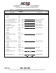

SYSTEM DESCRIPTION AND INSTALLATION MANUAL
TCAS 3000 Traffic Alert and Collision Avoidance System
34−43−23
Use or disclosure of information on this page is subject to the restrictions in the proprietary notice of this document.
Page 3−23
15 Dec 2005
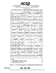
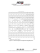
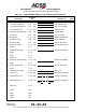
C. Control Panels
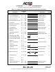
Table 3−1 thru Table 3−3 contain interconnect information for the various control panels.
Table 3−1 contains the interconnect data for the ACSS Dual Mode S/TCAS Control Panel,
Part No. 4052190−902, −904, −906 and −908. Table 3−2 contains the interconnect data
for the ACSS ATCRBS−Mode S/TCAS Control Panel, Part No. 4052190−903, −905, −907
and −909. Table 3−3 contains the interconnect data for the Gables G7130 series control
panels.
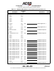
Table 3−1. ACSS Dual Mode S Control Panel Interconnect Data
I/O Description
Connector
Pin
Connects To Notes
(I) 5 V ac Panel Lighting (C) J1−1 (20) Acft Lighting Source
(I) 5 V ac Panel Lighting (H) J1−2 (20) Acft Lighting Source
(I) 115 V ac Input Power (H) J1−3 (20) Acft 115 V ac Supply
(I) 115 V ac Return (C) J1−4 (20) Acft ac Ground
(O) Antenna Transfer Discrete J1−5 (22) Antenna Relay 1
(I) dc Ground J1−6 (22) Acft dc Ground
(O) Standby/On J1−7 (22) Transponder No.1
(I) Chassis Ground J1−8 (22) Airframe Ground 2
(I) Functional Test J1−9 (22) Remote Test Switch
(O) Warning & Caution J1−10 (22) Remote Warn System
Spare J1−11
(I) XPDR Fail No.2 Input J1−12 (22) Transponder No.1
Spare J1−13
Spare J1−14
Reserved J1−15
(O) Alt Source Select Discrete J1−16 (22) Transponder No.1
Spare J1−17
(I) Monitor Lamp Pwr J1−18 (20) 28 V dc, 2A Source
Spare J1−19
(I) XPDR Fail No.1 Input J1−20 (22) See J1−12 4
(I) Lamp Test J1−21 (22) Rmt Lamp Test Switch
(O) ARINC 429 (A) Out J1−22 (22) S T S
||
Transponder No.1 3
(O) ARINC 429 (B) Out J1−23 (22) STS
GND
ll
GND
Transponder No.1 3