
User's Manual
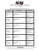
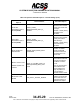
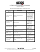
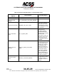
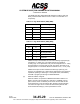
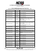
Table Of Contents
- T3CAS_Section_5
- 5 Adjustment/Test
- 1. General
- 2. Equipment
- 3. Initial Harness Checkout (New Installations Only)
- 4. System Self-Tests
- 5. Return-to-Service Test
- 6. Operational Software Loading Using an ARINC 615A Portable Data Loader or Compact Flash Card
- 7. Downloading Information from the TP3PCAS Using a CF Card
- 1. Obtain a New or Blank Compact Flash (CF) card.
- 2. Copy to the New or Blank CF card the appropriate ‘Header File’
- a) Header files are files copied to the New or Blank CF card that will instruct the computer unit what is desired to be downloaded.
- b) Header files needed to download Maintenance Data, Event Data and CRC Part Numbers can be obtained from ACSS Customer Services at +1-623-445-7070 or crc.acss@l-3com.com.
- 3. For downloading Maintenance Data, Event Data or CRC Part Numbers the aircraft does not need to be in an on-ground configuration.
- 4. Apply power to the computer unit.
- 5. Insert the CF card.
- 6. For ACSS part numbers 9005000-10000, -10101, -10202, and -10204 the DATA STATUS LED will UblinkU green once; this indicates the unit recognized that a CF card was inserted.
- 7. For ACSS part numbers 9005000-11203, -11801 and -55801 the DATA STATUS LED will UblinkU green while reading the header file and performing the action defined in the header file.
- 8. Flight Data Recording
- 1. T3CAS part numbers 9005000-10000, -10101, -10202, and -10204 only support FAT16 CF card formatting. T3CAS part numbers 9005000-11203, -11801 and -55801 support both FAT16 and FAT32 CF card formatting.
- B. Flight Data
- 1. Obtain a New or Blank CF Card.
- 2. Copy to the New or Blank CF Card the Appropriate Header File.
- 3. Header files are files copied to the New or Blank CF card that will instruct the computer unit what is desired to be downloaded.
- 4. For Flight Data Recording, the aircraft does not need to be in an on-ground configuration.
- 5. Apply power to the computer unit.
- 6. Insert the CF card.
- B. Flight Data
- 9. Downloaded Maintenance Data, Event Data And Flight Data May Be Sent To ACSS Customer Services For Analysis
- 5 Adjustment/Test
- T3CAS_Section_6
- T3CAS_Section_7
- 7 Maintenance Practices
- 1. General
- 2. Equipment and Materials
- 3. Procedure for the TP3PCAS Computer Unit
- 4. Procedure for the APM (Not applicable for part numbers 9005000-10000, -10101, -10202, -10204, or -11203)
- 5. Procedure for the Directional Antenna
- 6. Procedure for the Omnidirectional Antenna (Applicable to part numbers 9005000-11203, -11801 and -55801)
- 7. Procedure for the Control Panel
- 8. Procedure for the VSI/TRA Display
- 9. Instructions for Continued Airworthiness, FAR Part 25.1529
- 7 Maintenance Practices
- T3CAS_Section_8
- T3CAS_Section_9
- T3CAS_Section_10
- T3CAS_Appendix_A

SYSTEM DESCRIPTION AND INSTALLATION MANUAL
T
3
CAS/Part No.9005000
(c) RS-422 Signals
The T
3
CAS card has an RS-422 Input bus which is multiplexed on the
same pins as an ARINC 429 Input bus. The RS-422 Input Bus meets the
electrical requirements in EIA/TIA-422-B.
The RS-422 Input Bus has an input impedance on each pin relative to
ground of ≥ 9k ohms and a differential input impedance between + and -
pins of ≥ 9k ohms.
NOTE:
This is due to the fact the input is multiplexed with an ARINC
429 Receiver.
The RS-422 Output Bus has an output impedance of 75 ±5 ohms
distributed equally between the + and - outputs.
(d) GPS Time Mark
The GPS Time Mark Input accepts RS-422 GPS Time Mark signals from
an ARINC-743A GPS.
The GPS Time Mark Output is used to provide an accurate timing
reference for GPS signals. The output has a differential RS-422 signal
format.
(4) Programmable Discrete Input/Output Pins
The Discrete signals addressed in this section are APM/ASDB
programmable input and output signals as shown in Table 4-12, Table
4-13, and Table 4-14. As new Aircraft configurations/ASDBs are defined,
the Discrete signals will be assigned to a particular input/output per
Appendix n (“n” denotes Appendix’ that are created as new Aircraft
Configurations are defined).
Table 4-12: APM/ASDB Programmable Discrete Inputs
(Applicable to Part Numbers 9005000-10000, -10101, -10202, -10204, -11203)
Digital Signal Definition
Pin#
Notes (Typical Allocation Shown)
Ground Discrete Input
RTP-5K
TAWS/XPDR #11: Max True Airspeed
Strobed Program Pin
Ground Discrete Input
RTP-6D
TAWS/XPDR #1: Aircraft Type
Strobed Program Pin
Ground Discrete Input
RTP-6F
TAWS/XPDR #2: Aircraft Type
Strobed Program Pin
Ground Discrete Input
RTP-6G
TAWS/XPDR #3: Lateral Position Priority
Strobed Program Pin
Ground Discrete Input
RTP-6J
TAWS/XPDR #4: Audio Menu Selection
Strobed Program Pin
Pub. No. 8600200-001, Revision 004
34-45-29
4-111
04 Nov 2014
Use or disclosure of information on this page is subject to the restrictions in the proprietary notice of this document.