
User's Manual
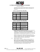
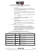
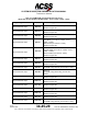
Table Of Contents
- T3CAS_Section_5
- 5 Adjustment/Test
- 1. General
- 2. Equipment
- 3. Initial Harness Checkout (New Installations Only)
- 4. System Self-Tests
- 5. Return-to-Service Test
- 6. Operational Software Loading Using an ARINC 615A Portable Data Loader or Compact Flash Card
- 7. Downloading Information from the TP3PCAS Using a CF Card
- 1. Obtain a New or Blank Compact Flash (CF) card.
- 2. Copy to the New or Blank CF card the appropriate ‘Header File’
- a) Header files are files copied to the New or Blank CF card that will instruct the computer unit what is desired to be downloaded.
- b) Header files needed to download Maintenance Data, Event Data and CRC Part Numbers can be obtained from ACSS Customer Services at +1-623-445-7070 or crc.acss@l-3com.com.
- 3. For downloading Maintenance Data, Event Data or CRC Part Numbers the aircraft does not need to be in an on-ground configuration.
- 4. Apply power to the computer unit.
- 5. Insert the CF card.
- 6. For ACSS part numbers 9005000-10000, -10101, -10202, and -10204 the DATA STATUS LED will UblinkU green once; this indicates the unit recognized that a CF card was inserted.
- 7. For ACSS part numbers 9005000-11203, -11801 and -55801 the DATA STATUS LED will UblinkU green while reading the header file and performing the action defined in the header file.
- 8. Flight Data Recording
- 1. T3CAS part numbers 9005000-10000, -10101, -10202, and -10204 only support FAT16 CF card formatting. T3CAS part numbers 9005000-11203, -11801 and -55801 support both FAT16 and FAT32 CF card formatting.
- B. Flight Data
- 1. Obtain a New or Blank CF Card.
- 2. Copy to the New or Blank CF Card the Appropriate Header File.
- 3. Header files are files copied to the New or Blank CF card that will instruct the computer unit what is desired to be downloaded.
- 4. For Flight Data Recording, the aircraft does not need to be in an on-ground configuration.
- 5. Apply power to the computer unit.
- 6. Insert the CF card.
- B. Flight Data
- 9. Downloaded Maintenance Data, Event Data And Flight Data May Be Sent To ACSS Customer Services For Analysis
- 5 Adjustment/Test
- T3CAS_Section_6
- T3CAS_Section_7
- 7 Maintenance Practices
- 1. General
- 2. Equipment and Materials
- 3. Procedure for the TP3PCAS Computer Unit
- 4. Procedure for the APM (Not applicable for part numbers 9005000-10000, -10101, -10202, -10204, or -11203)
- 5. Procedure for the Directional Antenna
- 6. Procedure for the Omnidirectional Antenna (Applicable to part numbers 9005000-11203, -11801 and -55801)
- 7. Procedure for the Control Panel
- 8. Procedure for the VSI/TRA Display
- 9. Instructions for Continued Airworthiness, FAR Part 25.1529
- 7 Maintenance Practices
- T3CAS_Section_8
- T3CAS_Section_9
- T3CAS_Section_10
- T3CAS_Appendix_A

SYSTEM DESCRIPTION AND INSTALLATION MANUAL
T
3
CAS/Part No.9005000
The ARINC 429 Sign Status Matrix Bit definitions for Binary data and
Binary Coded Decimal data are shown in Table 4-10 and Table 4-11
respectively.
Table 4-10: Sign Status Matrix (SSM) (BNR)
BITS
Meaning
30
31
0 0 Failure Warning
0 1 No Computed Data
1
0
Functional Test
1
1
Normal Operation
Table 4-11: Sign Status Matrix (SSM) [BCD]
BITS
Meaning
30 31
0 0 North/Plus
0
1
No Computed Data
1
0
Functional Test
1
1
Undefined
ARINC 429 inputs are classified as one of the following: high-speed (H),
low-speed (L) or either (H/L). The A429 receivers are capable of
receiving high- or low-speed data. The ports are designated H or L if they
are designated for a function with a known bus speed, otherwise H/L is
assigned (there is no hardware difference between the H, L or H/L ports).
ARINC 429 outputs are also classified as either high-speed (H), low-
speed (L) or selectable (H/L). A429 outputs designated as H/L speed are
capable of operating in either high- or low-speed modes, selectable by
the APM or program pins through the ASDB database.
(b) Ethernet 10 Base-T Signals
Ethernet 10 Base-T is specified in IEEE Standard 802.3 Ethernet 10
Base-T provides communication at a data rate of 10 MBPS over two
pairs of wires, where one twisted pair is used to receive data and the
other twisted pair is used to transmit data. Segments of approximately
100 meters in length can be constructed when twisted pair wire that
meets the EIA/TIA Category 3 wire specifications is used.
4-110
04 Nov 2014
34-45-29
Pub. No. 8600200-001, Revision 004
Use or disclosure of information on this page is subject to the restrictions in the proprietary notice of this document.