
User's Manual
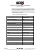
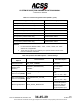
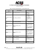
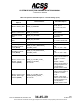
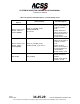
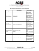
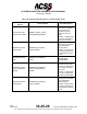
Table Of Contents
- T3CAS_Section_5
- 5 Adjustment/Test
- 1. General
- 2. Equipment
- 3. Initial Harness Checkout (New Installations Only)
- 4. System Self-Tests
- 5. Return-to-Service Test
- 6. Operational Software Loading Using an ARINC 615A Portable Data Loader or Compact Flash Card
- 7. Downloading Information from the TP3PCAS Using a CF Card
- 1. Obtain a New or Blank Compact Flash (CF) card.
- 2. Copy to the New or Blank CF card the appropriate ‘Header File’
- a) Header files are files copied to the New or Blank CF card that will instruct the computer unit what is desired to be downloaded.
- b) Header files needed to download Maintenance Data, Event Data and CRC Part Numbers can be obtained from ACSS Customer Services at +1-623-445-7070 or crc.acss@l-3com.com.
- 3. For downloading Maintenance Data, Event Data or CRC Part Numbers the aircraft does not need to be in an on-ground configuration.
- 4. Apply power to the computer unit.
- 5. Insert the CF card.
- 6. For ACSS part numbers 9005000-10000, -10101, -10202, and -10204 the DATA STATUS LED will UblinkU green once; this indicates the unit recognized that a CF card was inserted.
- 7. For ACSS part numbers 9005000-11203, -11801 and -55801 the DATA STATUS LED will UblinkU green while reading the header file and performing the action defined in the header file.
- 8. Flight Data Recording
- 1. T3CAS part numbers 9005000-10000, -10101, -10202, and -10204 only support FAT16 CF card formatting. T3CAS part numbers 9005000-11203, -11801 and -55801 support both FAT16 and FAT32 CF card formatting.
- B. Flight Data
- 1. Obtain a New or Blank CF Card.
- 2. Copy to the New or Blank CF Card the Appropriate Header File.
- 3. Header files are files copied to the New or Blank CF card that will instruct the computer unit what is desired to be downloaded.
- 4. For Flight Data Recording, the aircraft does not need to be in an on-ground configuration.
- 5. Apply power to the computer unit.
- 6. Insert the CF card.
- B. Flight Data
- 9. Downloaded Maintenance Data, Event Data And Flight Data May Be Sent To ACSS Customer Services For Analysis
- 5 Adjustment/Test
- T3CAS_Section_6
- T3CAS_Section_7
- 7 Maintenance Practices
- 1. General
- 2. Equipment and Materials
- 3. Procedure for the TP3PCAS Computer Unit
- 4. Procedure for the APM (Not applicable for part numbers 9005000-10000, -10101, -10202, -10204, or -11203)
- 5. Procedure for the Directional Antenna
- 6. Procedure for the Omnidirectional Antenna (Applicable to part numbers 9005000-11203, -11801 and -55801)
- 7. Procedure for the Control Panel
- 8. Procedure for the VSI/TRA Display
- 9. Instructions for Continued Airworthiness, FAR Part 25.1529
- 7 Maintenance Practices
- T3CAS_Section_8
- T3CAS_Section_9
- T3CAS_Section_10
- T3CAS_Appendix_A

SYSTEM DESCRIPTION AND INSTALLATION MANUAL
T
3
CAS/Part No.9005000
Table 4-7: Callout Configuration Items (NOTE 1) (cont)
Configuration Option
ACD Setting Option
50-ft (15.24-m) Callout Enable Flag
Enable/Disable Callout
40-ft (12.192-m) Callout Enable Flag
Enable/Disable Callout
35-ft (10.668-m) Callout Enable Flag Enable/Disable Callout
35-ft (10.668-m) (Tone) Callout Enable Flag Enable/Disable Callout Tone
30-ft (9.144-m) Callout Enable Flag
Enable/Disable Callout
20-ft (6.096-m) Callout Enable Flag
Enable/Disable Callout
20-ft (6.096-m) (Tone) Callout Enable Flag
Enable/Disable Callout Tone
10-ft (3.048-m) Callout Enable Flag Enable/Disable Callout
NOTES:
1.
For Part Numbers 9005000-10000, -10101, -10202, -10204, and -11203
callouts are not applicable.
2.
These items should not be modified by the operator without further review
from the certification authorities.
Table 4-8: Operator Selectable Options – Default Settings
Operator Selectable
Options
Data Parameter Selectable Option
Aircraft Configuration
Data Part Number
ACD_PART_NUMBER
up to 23 ASCII
characters
Aircraft Registration
Number (Tail
Number)
AIRCRAFT_REGISTRATION_
NUMBER
up to 23 ASCII
characters
Alert High-Impedance
Volume Level (NOTE)
HIGH_IMPEDANCE_VOLUME
_LEVEL
integer in the range 0 ..
255
( min = 0, max = 255)
Alert Low-Impedance
Volume Level (NOTE)
LOW_IMPEDANCE_VOLUME_
LEVEL
integer in the range 0 ..
255
( min = 0, max = 255)
Bank Angle Repetition BANK_ANGLE_REPETITION
1, 2, 3, 4, Infinity -
T
3
CAS will repeat the
Bank Angle Warning
based on the Bank
Angle Repetition input.
Pub. No. 8600200-001, Revision 004
34-45-29
4-97
04 Nov 2014
Use or disclosure of information on this page is subject to the restrictions in the proprietary notice of this document.