
User's Manual
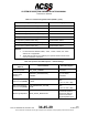
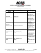
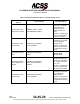
Table Of Contents
- T3CAS_Section_5
- 5 Adjustment/Test
- 1. General
- 2. Equipment
- 3. Initial Harness Checkout (New Installations Only)
- 4. System Self-Tests
- 5. Return-to-Service Test
- 6. Operational Software Loading Using an ARINC 615A Portable Data Loader or Compact Flash Card
- 7. Downloading Information from the TP3PCAS Using a CF Card
- 1. Obtain a New or Blank Compact Flash (CF) card.
- 2. Copy to the New or Blank CF card the appropriate ‘Header File’
- a) Header files are files copied to the New or Blank CF card that will instruct the computer unit what is desired to be downloaded.
- b) Header files needed to download Maintenance Data, Event Data and CRC Part Numbers can be obtained from ACSS Customer Services at +1-623-445-7070 or crc.acss@l-3com.com.
- 3. For downloading Maintenance Data, Event Data or CRC Part Numbers the aircraft does not need to be in an on-ground configuration.
- 4. Apply power to the computer unit.
- 5. Insert the CF card.
- 6. For ACSS part numbers 9005000-10000, -10101, -10202, and -10204 the DATA STATUS LED will UblinkU green once; this indicates the unit recognized that a CF card was inserted.
- 7. For ACSS part numbers 9005000-11203, -11801 and -55801 the DATA STATUS LED will UblinkU green while reading the header file and performing the action defined in the header file.
- 8. Flight Data Recording
- 1. T3CAS part numbers 9005000-10000, -10101, -10202, and -10204 only support FAT16 CF card formatting. T3CAS part numbers 9005000-11203, -11801 and -55801 support both FAT16 and FAT32 CF card formatting.
- B. Flight Data
- 1. Obtain a New or Blank CF Card.
- 2. Copy to the New or Blank CF Card the Appropriate Header File.
- 3. Header files are files copied to the New or Blank CF card that will instruct the computer unit what is desired to be downloaded.
- 4. For Flight Data Recording, the aircraft does not need to be in an on-ground configuration.
- 5. Apply power to the computer unit.
- 6. Insert the CF card.
- B. Flight Data
- 9. Downloaded Maintenance Data, Event Data And Flight Data May Be Sent To ACSS Customer Services For Analysis
- 5 Adjustment/Test
- T3CAS_Section_6
- T3CAS_Section_7
- 7 Maintenance Practices
- 1. General
- 2. Equipment and Materials
- 3. Procedure for the TP3PCAS Computer Unit
- 4. Procedure for the APM (Not applicable for part numbers 9005000-10000, -10101, -10202, -10204, or -11203)
- 5. Procedure for the Directional Antenna
- 6. Procedure for the Omnidirectional Antenna (Applicable to part numbers 9005000-11203, -11801 and -55801)
- 7. Procedure for the Control Panel
- 8. Procedure for the VSI/TRA Display
- 9. Instructions for Continued Airworthiness, FAR Part 25.1529
- 7 Maintenance Practices
- T3CAS_Section_8
- T3CAS_Section_9
- T3CAS_Section_10
- T3CAS_Appendix_A

SYSTEM DESCRIPTION AND INSTALLATION MANUAL
T
3
CAS/Part No.9005000
Verification of the correct APM contents may be accomplished by the RS-232
port or on the TAWS display. After the APM is programmed, the T
3
CAS, will
output the Aircraft Type Data part number and the installation option settings to
the RS-232 port. Additionally, it will display the APM configuration information on
the TAWS display. The data contained in the APM is recorded as part of the
aircraft configuration data. The software in the T
3
CAS unit checks the CRC of the
data to ensure the file is not corrupted.
Table 4-7: Callout Configuration Items (NOTE 1)
Configuration Option
ACD Setting Option
Callout Enable Flag [1]
NOTE 2)
Enable/Disable Callouts
Bank Angle Callout Enable Flag
Enable/Disable Bank Angle
Callout
DH/MDA Switch Available Flag Enable/Disable
Decision Height Callout Enable Flag Enable/Disable DH Callout
Minimums Callout Enable Flag
Enable/Disable Minimums Callout
Minimums-Minimums Callout Enable Flag
Enable/Disable Callout
Approaching Decision Height Callout Enable Flag
Enable/Disable Approaching DH
Callout
Approaching Minimums Callout Enable Flag
Enable/Disable Approaching
Minimums Callout
2500-ft (762-m) Callout Enable Flag
Enable/Disable Callout
1000-ft (304.8-m)Callout Enable Flag
Enable/Disable Callout
500-ft (152.4-m) Callout Enable Flag
(NOTE 2)
Enable/Disable Callout
500-ft (152.4-m) (Tone) Callout Enable Flag
(NOTE 2)
Enable/Disable Callout Tone
400-ft (121.92-m) Callout Enable Flag
Enable/Disable Callout
300-ft (91.44-m) Callout Enable Flag
Enable/Disable Callout
200-ft (60.96-m) Callout Enable Flag
Enable/Disable Callout
100-ft (30.48-m) Callout Enable Flag Enable/Disable Callout
100-ft (30.48-m) (Tone) Callout Enable Flag Enable/Disable Callout Tone
80-ft (24.384-m) Callout Enable Flag Enable/Disable Callout
60-ft (18.288-m) Callout Enable Flag
Enable/Disable Callout
4-96
04 Nov 2014
34-45-29
Pub. No. 8600200-001, Revision 004
Use or disclosure of information on this page is subject to the restrictions in the proprietary notice of this document.