
User's Manual
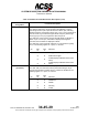
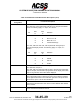
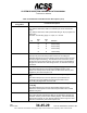
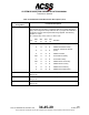
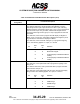
Table Of Contents
- T3CAS_Section_5
- 5 Adjustment/Test
- 1. General
- 2. Equipment
- 3. Initial Harness Checkout (New Installations Only)
- 4. System Self-Tests
- 5. Return-to-Service Test
- 6. Operational Software Loading Using an ARINC 615A Portable Data Loader or Compact Flash Card
- 7. Downloading Information from the TP3PCAS Using a CF Card
- 1. Obtain a New or Blank Compact Flash (CF) card.
- 2. Copy to the New or Blank CF card the appropriate ‘Header File’
- a) Header files are files copied to the New or Blank CF card that will instruct the computer unit what is desired to be downloaded.
- b) Header files needed to download Maintenance Data, Event Data and CRC Part Numbers can be obtained from ACSS Customer Services at +1-623-445-7070 or crc.acss@l-3com.com.
- 3. For downloading Maintenance Data, Event Data or CRC Part Numbers the aircraft does not need to be in an on-ground configuration.
- 4. Apply power to the computer unit.
- 5. Insert the CF card.
- 6. For ACSS part numbers 9005000-10000, -10101, -10202, and -10204 the DATA STATUS LED will UblinkU green once; this indicates the unit recognized that a CF card was inserted.
- 7. For ACSS part numbers 9005000-11203, -11801 and -55801 the DATA STATUS LED will UblinkU green while reading the header file and performing the action defined in the header file.
- 8. Flight Data Recording
- 1. T3CAS part numbers 9005000-10000, -10101, -10202, and -10204 only support FAT16 CF card formatting. T3CAS part numbers 9005000-11203, -11801 and -55801 support both FAT16 and FAT32 CF card formatting.
- B. Flight Data
- 1. Obtain a New or Blank CF Card.
- 2. Copy to the New or Blank CF Card the Appropriate Header File.
- 3. Header files are files copied to the New or Blank CF card that will instruct the computer unit what is desired to be downloaded.
- 4. For Flight Data Recording, the aircraft does not need to be in an on-ground configuration.
- 5. Apply power to the computer unit.
- 6. Insert the CF card.
- B. Flight Data
- 9. Downloaded Maintenance Data, Event Data And Flight Data May Be Sent To ACSS Customer Services For Analysis
- 5 Adjustment/Test
- T3CAS_Section_6
- T3CAS_Section_7
- 7 Maintenance Practices
- 1. General
- 2. Equipment and Materials
- 3. Procedure for the TP3PCAS Computer Unit
- 4. Procedure for the APM (Not applicable for part numbers 9005000-10000, -10101, -10202, -10204, or -11203)
- 5. Procedure for the Directional Antenna
- 6. Procedure for the Omnidirectional Antenna (Applicable to part numbers 9005000-11203, -11801 and -55801)
- 7. Procedure for the Control Panel
- 8. Procedure for the VSI/TRA Display
- 9. Instructions for Continued Airworthiness, FAR Part 25.1529
- 7 Maintenance Practices
- T3CAS_Section_8
- T3CAS_Section_9
- T3CAS_Section_10
- T3CAS_Appendix_A

SYSTEM DESCRIPTION AND INSTALLATION MANUAL
T
3
CAS/Part No.9005000
Table 4-6: ACSS 55-Pin VSI/TRA Interface Descriptions (cont)
Connector Pin
Designation
Functional Description
J1-52
PRESSURE TRANSDUCER MODULE +15 V dc POWER OUTPUT:
Connects to PTM pin 5. See pin 50.
3. TAWS/RWS and Transponder Specifications
The Ground Collision Avoidance Module (GCAM) function performs the core TAWS and reactive
windshear detection processing. Inputs to the GCAM are aircraft state variables, aircraft
performance models, the combined terrain and airport database, aircraft discretes, and ARINC
label busses. The outputs from the GCAM are the TAWS alerts, reactive windshear (RWS) alerts,
and the terrain display buffers.
The TAWS/RWS and Transponder input data is attained from a variety of aircraft LRUs
depending on the configuration of the specific aircraft. Since the source of the TAWS/RWS input
data is primarily unknown until a Customer Worksheet (Appendix A) and aircraft survey have
been completed, most of the ARINC 600 connector pins are configurable. Once the origin of the
TAWS/RWS input data has been determined an Aircraft Specific Data Base (ASDB) is generated
by ACSS that defines the pin assignments for that specific aircraft. At installation time, the ASDB
is loaded into the aircraft’s Aircraft Personality Module (APM) which then remains with the aircraft
throughout any T
3
CAS LRU removal/replacements to retain the aircraft configuration data. For
part numbers 9005000-10000, -10101, -10202, -10204, and -11203, the ASDB is contained
internally to the T
3
CAS unit since the APM is not applicable. Several ASDBs are provided to
support the various aircraft types and Pin Programming is used to select the appropriate ASDB
for the desired configuration
In addition to the configurable pins, the TAWS/RWS also contains some permanent or non-
configurable pin assignments as well as some pin assignments that are shared with the TCAS
functionality.
This section is organized in a generic format to accommodate the dynamic, aircraft dependant pin
assignments. The flow for configurable pin assignments is as follows:
● An aircraft configuration type is determined based on the equipment installed.
● Using the aircraft configuration data, the pin assignments are engineered, assigned and
documented in the ASDB system requirements.
● An Aircraft Configuration Table is then generated in Appendix B of this document that details
the specifics of the equipment installed on the new aircraft (columns) and assigns an Aircraft
Installation Number to the newly identified aircraft installation type (rows).
4-92
04 Nov 2014
34-45-29
Pub. No. 8600200-001, Revision 004
Use or disclosure of information on this page is subject to the restrictions in the proprietary notice of this document.