
User's Manual
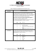
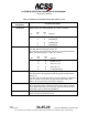
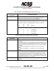
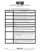
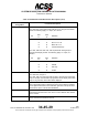
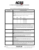
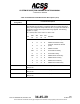
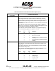
Table Of Contents
- T3CAS_Section_5
- 5 Adjustment/Test
- 1. General
- 2. Equipment
- 3. Initial Harness Checkout (New Installations Only)
- 4. System Self-Tests
- 5. Return-to-Service Test
- 6. Operational Software Loading Using an ARINC 615A Portable Data Loader or Compact Flash Card
- 7. Downloading Information from the TP3PCAS Using a CF Card
- 1. Obtain a New or Blank Compact Flash (CF) card.
- 2. Copy to the New or Blank CF card the appropriate ‘Header File’
- a) Header files are files copied to the New or Blank CF card that will instruct the computer unit what is desired to be downloaded.
- b) Header files needed to download Maintenance Data, Event Data and CRC Part Numbers can be obtained from ACSS Customer Services at +1-623-445-7070 or crc.acss@l-3com.com.
- 3. For downloading Maintenance Data, Event Data or CRC Part Numbers the aircraft does not need to be in an on-ground configuration.
- 4. Apply power to the computer unit.
- 5. Insert the CF card.
- 6. For ACSS part numbers 9005000-10000, -10101, -10202, and -10204 the DATA STATUS LED will UblinkU green once; this indicates the unit recognized that a CF card was inserted.
- 7. For ACSS part numbers 9005000-11203, -11801 and -55801 the DATA STATUS LED will UblinkU green while reading the header file and performing the action defined in the header file.
- 8. Flight Data Recording
- 1. T3CAS part numbers 9005000-10000, -10101, -10202, and -10204 only support FAT16 CF card formatting. T3CAS part numbers 9005000-11203, -11801 and -55801 support both FAT16 and FAT32 CF card formatting.
- B. Flight Data
- 1. Obtain a New or Blank CF Card.
- 2. Copy to the New or Blank CF Card the Appropriate Header File.
- 3. Header files are files copied to the New or Blank CF card that will instruct the computer unit what is desired to be downloaded.
- 4. For Flight Data Recording, the aircraft does not need to be in an on-ground configuration.
- 5. Apply power to the computer unit.
- 6. Insert the CF card.
- B. Flight Data
- 9. Downloaded Maintenance Data, Event Data And Flight Data May Be Sent To ACSS Customer Services For Analysis
- 5 Adjustment/Test
- T3CAS_Section_6
- T3CAS_Section_7
- 7 Maintenance Practices
- 1. General
- 2. Equipment and Materials
- 3. Procedure for the TP3PCAS Computer Unit
- 4. Procedure for the APM (Not applicable for part numbers 9005000-10000, -10101, -10202, -10204, or -11203)
- 5. Procedure for the Directional Antenna
- 6. Procedure for the Omnidirectional Antenna (Applicable to part numbers 9005000-11203, -11801 and -55801)
- 7. Procedure for the Control Panel
- 8. Procedure for the VSI/TRA Display
- 9. Instructions for Continued Airworthiness, FAR Part 25.1529
- 7 Maintenance Practices
- T3CAS_Section_8
- T3CAS_Section_9
- T3CAS_Section_10
- T3CAS_Appendix_A

SYSTEM DESCRIPTION AND INSTALLATION MANUAL
T
3
CAS/Part No.9005000
Table 4-6: ACSS 55-Pin VSI/TRA Interface Descriptions (cont)
Connector Pin
Designation
Functional Description
J1-22
CONFIGURATION STRAP #8 INPUT (NO):
For -84X and -86X units, CS8 is not used and pin J1-22 must remain
Open.
For -88X and -89X units, CS8 is paired with CS3 (pin 35) to program the
Filter Time
Constant. The following apply: O = Open, G = Ground
Pin
CS8
22
CS3
35
Definition
O
O
5.0-sec Delay
O
G
6.4-sec Delay
G O 3.2-sec Delay
G G 1.6-sec Delay
J1-23, 24
REMOTE LIGHT SENSOR INPUT: (J1-23 HIGH, J1-24 LOW )
This input at pins 23 and 24 provides a means of controlling the
VSI/TRA back lighting via a remote light sensor already present in some
aircraft (Douglas and Boeing). The VSI/TRA has its own built-in sensor
and therefore a remote light sensor need not be used in all installations.
Program the VSI/TRA for a remote light sensor, as described under pin
34 and 35.
J1-25, 44
ARINC 429 TCAS BUS INPUT: [J1-25 (A), J1-44 (B)]
This differential pair input is a high-speed ARINC 429 bus (100k
bit/second nominal) that receives Traffic and Resolution Advisory data
supplied by the TCAS computer unit.
J1-26, 45
ARINC 429 VERTICAL SPEED NO.2 BUS INPUT: [J1-26 (A), J1-45
(B)]
This differential pair input is a low-speed bus (12.5k bits/second
nominal) that receives ARINC 429 vertical speed data from the
secondary (#2) digital ADC or the #2 PTM.
J1-27, 46
ARINC 429 INERTIAL REFERENCE SYSTEM BUS INPUT: [J1-27 (A),
J1-46 (B)]
This differential pair input is a low-speed ARINC 429 bus (12.5k
bits/second nominal) that receives vertical speed data from an Inertial
Reference System.
J1-28
RA VALID DISCRETE OUTPUT:
This output discrete indicates the ability of the VSI/TRA to perform as a
resolution advisory and/or a traffic advisory display. If the VSI/TRA fails,
this discrete presents an open. Normal operation causes a ground. This
discrete is monitored by the TCAS computer unit.
4-88
04 Nov 2014
34-45-29
Pub. No. 8600200-001, Revision 004
Use or disclosure of information on this page is subject to the restrictions in the proprietary notice of this document.