
User's Manual
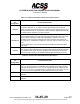
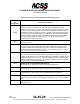
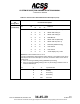
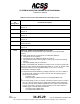
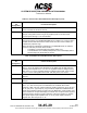
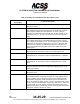
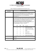
Table Of Contents
- T3CAS_Section_5
- 5 Adjustment/Test
- 1. General
- 2. Equipment
- 3. Initial Harness Checkout (New Installations Only)
- 4. System Self-Tests
- 5. Return-to-Service Test
- 6. Operational Software Loading Using an ARINC 615A Portable Data Loader or Compact Flash Card
- 7. Downloading Information from the TP3PCAS Using a CF Card
- 1. Obtain a New or Blank Compact Flash (CF) card.
- 2. Copy to the New or Blank CF card the appropriate ‘Header File’
- a) Header files are files copied to the New or Blank CF card that will instruct the computer unit what is desired to be downloaded.
- b) Header files needed to download Maintenance Data, Event Data and CRC Part Numbers can be obtained from ACSS Customer Services at +1-623-445-7070 or crc.acss@l-3com.com.
- 3. For downloading Maintenance Data, Event Data or CRC Part Numbers the aircraft does not need to be in an on-ground configuration.
- 4. Apply power to the computer unit.
- 5. Insert the CF card.
- 6. For ACSS part numbers 9005000-10000, -10101, -10202, and -10204 the DATA STATUS LED will UblinkU green once; this indicates the unit recognized that a CF card was inserted.
- 7. For ACSS part numbers 9005000-11203, -11801 and -55801 the DATA STATUS LED will UblinkU green while reading the header file and performing the action defined in the header file.
- 8. Flight Data Recording
- 1. T3CAS part numbers 9005000-10000, -10101, -10202, and -10204 only support FAT16 CF card formatting. T3CAS part numbers 9005000-11203, -11801 and -55801 support both FAT16 and FAT32 CF card formatting.
- B. Flight Data
- 1. Obtain a New or Blank CF Card.
- 2. Copy to the New or Blank CF Card the Appropriate Header File.
- 3. Header files are files copied to the New or Blank CF card that will instruct the computer unit what is desired to be downloaded.
- 4. For Flight Data Recording, the aircraft does not need to be in an on-ground configuration.
- 5. Apply power to the computer unit.
- 6. Insert the CF card.
- B. Flight Data
- 9. Downloaded Maintenance Data, Event Data And Flight Data May Be Sent To ACSS Customer Services For Analysis
- 5 Adjustment/Test
- T3CAS_Section_6
- T3CAS_Section_7
- 7 Maintenance Practices
- 1. General
- 2. Equipment and Materials
- 3. Procedure for the TP3PCAS Computer Unit
- 4. Procedure for the APM (Not applicable for part numbers 9005000-10000, -10101, -10202, -10204, or -11203)
- 5. Procedure for the Directional Antenna
- 6. Procedure for the Omnidirectional Antenna (Applicable to part numbers 9005000-11203, -11801 and -55801)
- 7. Procedure for the Control Panel
- 8. Procedure for the VSI/TRA Display
- 9. Instructions for Continued Airworthiness, FAR Part 25.1529
- 7 Maintenance Practices
- T3CAS_Section_8
- T3CAS_Section_9
- T3CAS_Section_10
- T3CAS_Appendix_A

SYSTEM DESCRIPTION AND INSTALLATION MANUAL
T
3
CAS/Part No.9005000
Table 4-5: ACSS 41-Pin VSI/TRA Interface Descriptions (cont)
Connector Pin
Designation
Functional Description
J1-30
ARINC 429 (A) VERTICAL SPEED NO.2 INPUT:
This is the secondary ARINC 429 input bus to the VSI/TRA. This pin
accepts high- or low-speed ARINC 429 vertical speed data (Label 212).
Its use is determined by the source select discrete and configuration
straps CS0 and CS1 (pins 31, 32 and 33 respectively).
Paired with pin 14.
J1-31
SOURCE SELECT DISCRETE INPUT (NO):
This discrete input is used in conjunction with configuration straps CS0
and CS1 to program the VSI/TRA to accept and use the vertical speed
data being supplied. In some installations, this discrete is connected to a
switch in the cockpit and is used to select between primary and
secondary ARINC 429 vertical speed inputs. It is hard-wired to
configuration strap common if ac or dc analog vertical speed inputs are
used. Cycle power to update to the new configuration.
The following applies: O = Open, G = Ground.
Pin
SS
31
CS0
32
CS1
33
Definition
O O O ARINC 429 HS Primary
G
O
O
ARINC 429 HS Secondary
O G O
Pressure Transducer Module
(PTM)
G
G
O
ARINC 575 dc
G
O
G
ARINC 565 ac
O G G ARINC 429 LS Primary
G
G
G
ARINC 429 LS Secondary
J1-32
CONFIGURATION STRAP #0 INPUT (NO):
See pin 31.
J1-33
CONFIGURATION STRAP #1 INPUT (NO):
See pin 31.
4-82
04 Nov 2014
34-45-29
Pub. No. 8600200-001, Revision 004
Use or disclosure of information on this page is subject to the restrictions in the proprietary notice of this document.