
User's Manual
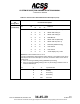
Table Of Contents
- T3CAS_Section_5
- 5 Adjustment/Test
- 1. General
- 2. Equipment
- 3. Initial Harness Checkout (New Installations Only)
- 4. System Self-Tests
- 5. Return-to-Service Test
- 6. Operational Software Loading Using an ARINC 615A Portable Data Loader or Compact Flash Card
- 7. Downloading Information from the TP3PCAS Using a CF Card
- 1. Obtain a New or Blank Compact Flash (CF) card.
- 2. Copy to the New or Blank CF card the appropriate ‘Header File’
- a) Header files are files copied to the New or Blank CF card that will instruct the computer unit what is desired to be downloaded.
- b) Header files needed to download Maintenance Data, Event Data and CRC Part Numbers can be obtained from ACSS Customer Services at +1-623-445-7070 or crc.acss@l-3com.com.
- 3. For downloading Maintenance Data, Event Data or CRC Part Numbers the aircraft does not need to be in an on-ground configuration.
- 4. Apply power to the computer unit.
- 5. Insert the CF card.
- 6. For ACSS part numbers 9005000-10000, -10101, -10202, and -10204 the DATA STATUS LED will UblinkU green once; this indicates the unit recognized that a CF card was inserted.
- 7. For ACSS part numbers 9005000-11203, -11801 and -55801 the DATA STATUS LED will UblinkU green while reading the header file and performing the action defined in the header file.
- 8. Flight Data Recording
- 1. T3CAS part numbers 9005000-10000, -10101, -10202, and -10204 only support FAT16 CF card formatting. T3CAS part numbers 9005000-11203, -11801 and -55801 support both FAT16 and FAT32 CF card formatting.
- B. Flight Data
- 1. Obtain a New or Blank CF Card.
- 2. Copy to the New or Blank CF Card the Appropriate Header File.
- 3. Header files are files copied to the New or Blank CF card that will instruct the computer unit what is desired to be downloaded.
- 4. For Flight Data Recording, the aircraft does not need to be in an on-ground configuration.
- 5. Apply power to the computer unit.
- 6. Insert the CF card.
- B. Flight Data
- 9. Downloaded Maintenance Data, Event Data And Flight Data May Be Sent To ACSS Customer Services For Analysis
- 5 Adjustment/Test
- T3CAS_Section_6
- T3CAS_Section_7
- 7 Maintenance Practices
- 1. General
- 2. Equipment and Materials
- 3. Procedure for the TP3PCAS Computer Unit
- 4. Procedure for the APM (Not applicable for part numbers 9005000-10000, -10101, -10202, -10204, or -11203)
- 5. Procedure for the Directional Antenna
- 6. Procedure for the Omnidirectional Antenna (Applicable to part numbers 9005000-11203, -11801 and -55801)
- 7. Procedure for the Control Panel
- 8. Procedure for the VSI/TRA Display
- 9. Instructions for Continued Airworthiness, FAR Part 25.1529
- 7 Maintenance Practices
- T3CAS_Section_8
- T3CAS_Section_9
- T3CAS_Section_10
- T3CAS_Appendix_A

SYSTEM DESCRIPTION AND INSTALLATION MANUAL
T
3
CAS/Part No.9005000
Table 4-4: Thales 41-Pin VSI-TCAS Interface Description (cont)
Connector
Pin
Designation
Functional Description
J1-32
CONFIGURATION STRAP #0 INPUT (NO):
See pin 31.
J1-33
CONFIGURATION STRAP #1 INPUT (NO):
See pin 31.
J1-34
CONFIGURATION STRAP #2 INPUT (NO):
See pin 31.
J1-35
CONFIGURATION STRAP #4 INPUT (NO):
See pin 17.
J1-36
SECONDARY ANALOG ac INPUT (LO):
ARINC 565 ADC
J1-37
SECONDARY SOURCE SELECT DISCRETE INPUT (NO):
See pin 31.
J1-38
VERTICAL SPEED VALID DISCRETE OUTPUT (NO):
This validity discrete is representative of the operation of the vertical speed
channel.
The state of this discrete corresponds to an invalid state (OPEN) if :
● The indicator is not energized
● The indicator is in the initialization phase on power up
● The vertical speed failure warning flag is in view (case of internal or external
failures)
● The self-test/display test pin is activated.
Definition of the OPEN state: Impedance in relation to the dc common greater than
100k ohms (open collector with an applicable voltage of +14 V dc to +32 than 100k
ohms (open collector with an applicable voltage of +14 V dc to +32 V dc).
A valid state is indicated by either:
1) A GROUND state characterized by a voltage of less than 3.5 V dc in relation to
dc commons with a maximum current of 20 mA, when the following types of
vertical speed are selected:
- Pneumatic input
- Digital inputs (per ARINC 429 HS or LS and digital ARINC 575).
or
2) A dc output voltage (+ 28 V dc nominal), the minimum value of which is equal to
VIN - (2 + 200 x I), where VIN is the greater of the primary vertical speed and
secondary vertical speed voltages available and I the output current expressed
in amps (0.02 A max.). This type of signal is present on the output when the
following types of vertical speed are selected:
- ac analogue input (ARINC 565)
- dc analogue input (ARINC 575).
4-78
04 Nov 2014
34-45-29
Pub. No. 8600200-001, Revision 004
Use or disclosure of information on this page is subject to the restrictions in the proprietary notice of this document.