
User's Manual
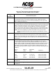
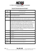
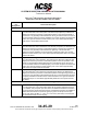
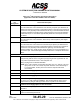
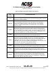
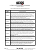
Table Of Contents
- T3CAS_Section_5
- 5 Adjustment/Test
- 1. General
- 2. Equipment
- 3. Initial Harness Checkout (New Installations Only)
- 4. System Self-Tests
- 5. Return-to-Service Test
- 6. Operational Software Loading Using an ARINC 615A Portable Data Loader or Compact Flash Card
- 7. Downloading Information from the TP3PCAS Using a CF Card
- 1. Obtain a New or Blank Compact Flash (CF) card.
- 2. Copy to the New or Blank CF card the appropriate ‘Header File’
- a) Header files are files copied to the New or Blank CF card that will instruct the computer unit what is desired to be downloaded.
- b) Header files needed to download Maintenance Data, Event Data and CRC Part Numbers can be obtained from ACSS Customer Services at +1-623-445-7070 or crc.acss@l-3com.com.
- 3. For downloading Maintenance Data, Event Data or CRC Part Numbers the aircraft does not need to be in an on-ground configuration.
- 4. Apply power to the computer unit.
- 5. Insert the CF card.
- 6. For ACSS part numbers 9005000-10000, -10101, -10202, and -10204 the DATA STATUS LED will UblinkU green once; this indicates the unit recognized that a CF card was inserted.
- 7. For ACSS part numbers 9005000-11203, -11801 and -55801 the DATA STATUS LED will UblinkU green while reading the header file and performing the action defined in the header file.
- 8. Flight Data Recording
- 1. T3CAS part numbers 9005000-10000, -10101, -10202, and -10204 only support FAT16 CF card formatting. T3CAS part numbers 9005000-11203, -11801 and -55801 support both FAT16 and FAT32 CF card formatting.
- B. Flight Data
- 1. Obtain a New or Blank CF Card.
- 2. Copy to the New or Blank CF Card the Appropriate Header File.
- 3. Header files are files copied to the New or Blank CF card that will instruct the computer unit what is desired to be downloaded.
- 4. For Flight Data Recording, the aircraft does not need to be in an on-ground configuration.
- 5. Apply power to the computer unit.
- 6. Insert the CF card.
- B. Flight Data
- 9. Downloaded Maintenance Data, Event Data And Flight Data May Be Sent To ACSS Customer Services For Analysis
- 5 Adjustment/Test
- T3CAS_Section_6
- T3CAS_Section_7
- 7 Maintenance Practices
- 1. General
- 2. Equipment and Materials
- 3. Procedure for the TP3PCAS Computer Unit
- 4. Procedure for the APM (Not applicable for part numbers 9005000-10000, -10101, -10202, -10204, or -11203)
- 5. Procedure for the Directional Antenna
- 6. Procedure for the Omnidirectional Antenna (Applicable to part numbers 9005000-11203, -11801 and -55801)
- 7. Procedure for the Control Panel
- 8. Procedure for the VSI/TRA Display
- 9. Instructions for Continued Airworthiness, FAR Part 25.1529
- 7 Maintenance Practices
- T3CAS_Section_8
- T3CAS_Section_9
- T3CAS_Section_10
- T3CAS_Appendix_A

SYSTEM DESCRIPTION AND INSTALLATION MANUAL
T
3
CAS/Part No.9005000
Table 4-3: Gables Control Panel Interface Descriptions (cont)
Connector
Pin
Designation
Functional Description
J1/J2-12
XPDR FAIL #2 INPUT: (J1/J2-12)
The G7130-XX ATC/TCAS control panel transponder fail annunciator is controlled
by this input. When the transponder is operating normally this input remains
grounded. Otherwise, the transponder opens this input to indicate a transponder
failure. The control panel turns the annunciator ON to alert the user of a
transponder malfunction. The transponder fail annunciator turns on only when the
failed transponder is selected by the XPDR 1-2 switch.
Connect this pin to the transponder XPDR FAIL #2 Discrete Output.
J1/J2-13
IDENT INPUT: (J1/J2-13)
The IDENT discrete input provides another means of activating the IDENT
function. This input allows the control panel to interface with an external IDENT
switch located in the Flight Deck. When the input is grounded, the IDENT function
is activated; otherwise it should remain open.
J1/J2-14
TRANSPONDER FAIL LOGIC DISCRETE INPUT: (TDR-94D ONLY) (J1/J2-14)
This input allows the control panel to use +28 V dc logic from a Collins TDR-94D
transponder to control the transponder fail annunciator. This input should not be
used unless a Collins TDR-94D transponder is used with this control panel.
J1/J2-15
AIR/GROUND SW DISCRETE OUTPUT: (J1/J2-15)
This output is directly connected to the AIR/GND discrete input (J1/J2-24). This
output can be routed directly to the transponder to disable it (Standby), and
terminate ATC code replies. J1 discrete logic operates independently from J2.
J1/J2-16
AIR DATA SOURCE OUTPUT: (J1/J2-16)
Ground/Open output that is dependent on the front panel ALT RPTG and XPDR
switch positions. This discrete output is enabled when altitude reporting is selected
in the ON mode. When altitude reporting is selected OFF, the J1/J2-16 output
remains in the OPEN state.
This discrete output is connected to the transponder AIR DATA SOURCE SELECT
Discrete Input.
J1/J2-18
MONITOR LAMP POWER INPUT: (J1-/J218)
These inputs are used as the input power source for the transponder fail
annunciator on the front panel of the control panel. The input supply voltage is a
dimmable +28 V dc at 200 mA maximum.
J1/J2-20
TRANSPONDER STRAPPING CONFIGURATION: (J1/J2-20)
This discrete input programs the control panel to operate, and be able to properly
interface to one of two types of transponder configurations. If this input is left
OPEN then the control panel operates in accordance with ACSS transponder
specifications. If the input is GROUNDED, it is programmed to operate in
accordance with Collins transponder specifications.
4-72
04 Nov 2014
34-45-29
Pub. No. 8600200-001, Revision 004
Use or disclosure of information on this page is subject to the restrictions in the proprietary notice of this document.