
User's Manual
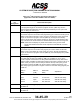
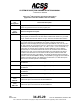
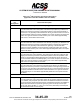
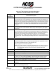
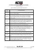
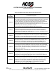
Table Of Contents
- T3CAS_Section_5
- 5 Adjustment/Test
- 1. General
- 2. Equipment
- 3. Initial Harness Checkout (New Installations Only)
- 4. System Self-Tests
- 5. Return-to-Service Test
- 6. Operational Software Loading Using an ARINC 615A Portable Data Loader or Compact Flash Card
- 7. Downloading Information from the TP3PCAS Using a CF Card
- 1. Obtain a New or Blank Compact Flash (CF) card.
- 2. Copy to the New or Blank CF card the appropriate ‘Header File’
- a) Header files are files copied to the New or Blank CF card that will instruct the computer unit what is desired to be downloaded.
- b) Header files needed to download Maintenance Data, Event Data and CRC Part Numbers can be obtained from ACSS Customer Services at +1-623-445-7070 or crc.acss@l-3com.com.
- 3. For downloading Maintenance Data, Event Data or CRC Part Numbers the aircraft does not need to be in an on-ground configuration.
- 4. Apply power to the computer unit.
- 5. Insert the CF card.
- 6. For ACSS part numbers 9005000-10000, -10101, -10202, and -10204 the DATA STATUS LED will UblinkU green once; this indicates the unit recognized that a CF card was inserted.
- 7. For ACSS part numbers 9005000-11203, -11801 and -55801 the DATA STATUS LED will UblinkU green while reading the header file and performing the action defined in the header file.
- 8. Flight Data Recording
- 1. T3CAS part numbers 9005000-10000, -10101, -10202, and -10204 only support FAT16 CF card formatting. T3CAS part numbers 9005000-11203, -11801 and -55801 support both FAT16 and FAT32 CF card formatting.
- B. Flight Data
- 1. Obtain a New or Blank CF Card.
- 2. Copy to the New or Blank CF Card the Appropriate Header File.
- 3. Header files are files copied to the New or Blank CF card that will instruct the computer unit what is desired to be downloaded.
- 4. For Flight Data Recording, the aircraft does not need to be in an on-ground configuration.
- 5. Apply power to the computer unit.
- 6. Insert the CF card.
- B. Flight Data
- 9. Downloaded Maintenance Data, Event Data And Flight Data May Be Sent To ACSS Customer Services For Analysis
- 5 Adjustment/Test
- T3CAS_Section_6
- T3CAS_Section_7
- 7 Maintenance Practices
- 1. General
- 2. Equipment and Materials
- 3. Procedure for the TP3PCAS Computer Unit
- 4. Procedure for the APM (Not applicable for part numbers 9005000-10000, -10101, -10202, -10204, or -11203)
- 5. Procedure for the Directional Antenna
- 6. Procedure for the Omnidirectional Antenna (Applicable to part numbers 9005000-11203, -11801 and -55801)
- 7. Procedure for the Control Panel
- 8. Procedure for the VSI/TRA Display
- 9. Instructions for Continued Airworthiness, FAR Part 25.1529
- 7 Maintenance Practices
- T3CAS_Section_8
- T3CAS_Section_9
- T3CAS_Section_10
- T3CAS_Appendix_A

SYSTEM DESCRIPTION AND INSTALLATION MANUAL
T
3
CAS/Part No.9005000
Table 4-3: Gables Control Panel Interface Descriptions
Connector
Pin
Designation
Functional Description
J1-1, 2
PANEL AND DISPLAY LIGHTING INPUT: (J1-1 HIGH, J1-2 LOW)
5-V ac, 2.3-A maximum lighting input for front panel and display lighting. Lighting is
provided by incandescent lamps.
J1/J2-3, 4
+28 V dc INPUT POWER: (J1/J2-3 HIGH, J1/J2-4 LOW)
The control panel is powered from a +28-V dc power bus. Two identical but
isolated power supplies provide the power requirements to each individual
electronic module that independently control transponder 1 and 2. Maximum
current is 2.5 A dc.
J1/J2-5
ANTENNA TRANSFER DISCRETE OUTPUT: (J1/J2-5)
This discrete output is used to provide the ability to switch a RF relay for dual
transponder installations that have only one set of antennas. These outputs from
J1 and J2 are linked to the XPDR 1-2 switch. The output is OPEN (+12 to +35 V
dc) when the transponder is in standby (inactive) mode, and GROUND (< +3.5 V
dc) when the transponder is in an active operational mode.
J1/J2-6
dc GROUND INPUT: (J1/J2-6)
Reference for all discrete inputs/outputs. Tied to aircraft dc ground.
J1/J2-7
STANDBY/ON OUTPUT: (J1/J2-7)
These discrete outputs (STANDBY/ON) will mimic the XPDR switch position
placing one transponder in Standby and the other in the ON (active) mode. Both
transponders will never be in the ON mode simultaneously. This output is
GROUND(< +3.5 V dc) when in Standby mode and OPEN (+12 to +35 V dc) when
in the ON mode. This output can sink 100 mA maximum.
Connect pin to transponder STANDBY/ON Discrete Input.
J1/J2-8
CHASSIS GROUND INPUT: (J1/J2-8)
Tied to airframe. Also used to connect ARINC 429 cable shields to the chassis.
J1/J2-9
FUNCTIONAL TEST INPUT: (J1/J2-9)
Functional test can also be initiated using this discrete input. When J1/J2-9 is
grounded, a functional test similar to pushing the TEST button on the front panel is
done.
J1/J2-10
WARNING AND CAUTION OUTPUT: (J1/J2-10)
This discrete output provides a low signal to a remote master warning system
when the control panel receives a Monitor Lamp fault indication from the active
transponder. Otherwise it provides 7 to 30 V dc or a resistance of >100k ohms to
ground. This output can sink 20 mA maximum.
Pub. No. 8600200-001, Revision 004
34-45-29
4-71
04 Nov 2014
Use or disclosure of information on this page is subject to the restrictions in the proprietary notice of this document.