
User's Manual
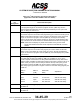
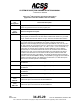
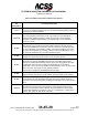
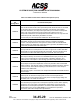
Table Of Contents
- T3CAS_Section_5
- 5 Adjustment/Test
- 1. General
- 2. Equipment
- 3. Initial Harness Checkout (New Installations Only)
- 4. System Self-Tests
- 5. Return-to-Service Test
- 6. Operational Software Loading Using an ARINC 615A Portable Data Loader or Compact Flash Card
- 7. Downloading Information from the TP3PCAS Using a CF Card
- 1. Obtain a New or Blank Compact Flash (CF) card.
- 2. Copy to the New or Blank CF card the appropriate ‘Header File’
- a) Header files are files copied to the New or Blank CF card that will instruct the computer unit what is desired to be downloaded.
- b) Header files needed to download Maintenance Data, Event Data and CRC Part Numbers can be obtained from ACSS Customer Services at +1-623-445-7070 or crc.acss@l-3com.com.
- 3. For downloading Maintenance Data, Event Data or CRC Part Numbers the aircraft does not need to be in an on-ground configuration.
- 4. Apply power to the computer unit.
- 5. Insert the CF card.
- 6. For ACSS part numbers 9005000-10000, -10101, -10202, and -10204 the DATA STATUS LED will UblinkU green once; this indicates the unit recognized that a CF card was inserted.
- 7. For ACSS part numbers 9005000-11203, -11801 and -55801 the DATA STATUS LED will UblinkU green while reading the header file and performing the action defined in the header file.
- 8. Flight Data Recording
- 1. T3CAS part numbers 9005000-10000, -10101, -10202, and -10204 only support FAT16 CF card formatting. T3CAS part numbers 9005000-11203, -11801 and -55801 support both FAT16 and FAT32 CF card formatting.
- B. Flight Data
- 1. Obtain a New or Blank CF Card.
- 2. Copy to the New or Blank CF Card the Appropriate Header File.
- 3. Header files are files copied to the New or Blank CF card that will instruct the computer unit what is desired to be downloaded.
- 4. For Flight Data Recording, the aircraft does not need to be in an on-ground configuration.
- 5. Apply power to the computer unit.
- 6. Insert the CF card.
- B. Flight Data
- 9. Downloaded Maintenance Data, Event Data And Flight Data May Be Sent To ACSS Customer Services For Analysis
- 5 Adjustment/Test
- T3CAS_Section_6
- T3CAS_Section_7
- 7 Maintenance Practices
- 1. General
- 2. Equipment and Materials
- 3. Procedure for the TP3PCAS Computer Unit
- 4. Procedure for the APM (Not applicable for part numbers 9005000-10000, -10101, -10202, -10204, or -11203)
- 5. Procedure for the Directional Antenna
- 6. Procedure for the Omnidirectional Antenna (Applicable to part numbers 9005000-11203, -11801 and -55801)
- 7. Procedure for the Control Panel
- 8. Procedure for the VSI/TRA Display
- 9. Instructions for Continued Airworthiness, FAR Part 25.1529
- 7 Maintenance Practices
- T3CAS_Section_8
- T3CAS_Section_9
- T3CAS_Section_10
- T3CAS_Appendix_A

SYSTEM DESCRIPTION AND INSTALLATION MANUAL
T
3
CAS/Part No.9005000
Table 4-2: T
3
CAS Computer Unit Interface Description
(Applicable to Part No. 9005000-11801 and -55801)
Connector
Pin
Designation
Functional Description
RBP-7D
Audio Tone Enable Program Pin (NO)
If this programming pin is connected to program common, (RBP-7K), all voice
announcements are delayed by one sec and are preceded by a tone. If pin is left
open, no delays or tones occur.
RBP-7E
Ground Display Mode Program Pin (NO)
The T
3
CAS computer unit monitors this programming pin to select the TCAS ground
display mode while the aircraft is on the ground. If the aircraft is on the ground and
this pin is connected to program common (RBP-7K), TCAS goes into standby
mode. If this pin is left open and the aircraft is on the ground, TCAS displays traffic
only. Aural and voice annunciations are inhibited while the aircraft is on the ground.
NOTE: TCAS does not display any traffic that it locates on the ground. TCAS
aircraft has WOW and intruder aircraft reports the same altitude or a lower
altitude.
RBP-7F
Display All Traffic Program Pin (NO)
The T
3
CAS computer unit monitors this program pin to select either the all traffic
display mode or the TA/RA only mode. If this pin is open, all traffic is displayed. If
this pin is connected to program common (RBP-7K), the TCAS displays only TA/RA
type intruders.
RBP-7G
Cable Delay Signal Program Pin (NO)
The cable delay program pins (RBP-7G, RBP-7H, and RBP-7J) convey to the
T
3
CAS computer unit the amount of delay differential between the top and bottom
antenna cables. Pin RBP-7G determines whether a time delay is added to the top or
bottom. If this pin is open, the time delay is added to the top. If this pin is ground
(connected to program pin RBP-7K), the time delay is added to the bottom. The
cable delay logic is given below. Program common for the cable delay program pins
is RBP-7K.
RBP-7H
(MSB)
RBP-7J
(LSB)
Differential
Delay
Adjustment
Open Open 0-50 nsec No Change
Open
Ground
51-150 nsec
Add 100 nsec delay
Ground
Open
151-250 nsec
Add 200 nsec delay
Ground Ground 251-350 nsec Add 300 nsec delay
RBP-7H
Cable Delay MSB Program (NO)
See RBP-7G.
RBP-7J
Cable Delay LSB Program Pin (NO)
See RBP-7G.
Pub. No. 8600200-001, Revision 004
34-45-29
4-63
04 Nov 2014
Use or disclosure of information on this page is subject to the restrictions in the proprietary notice of this document.