
User's Manual
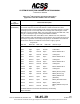
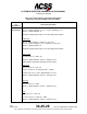
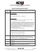
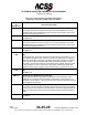
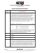
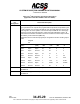
Table Of Contents
- T3CAS_Section_5
- 5 Adjustment/Test
- 1. General
- 2. Equipment
- 3. Initial Harness Checkout (New Installations Only)
- 4. System Self-Tests
- 5. Return-to-Service Test
- 6. Operational Software Loading Using an ARINC 615A Portable Data Loader or Compact Flash Card
- 7. Downloading Information from the TP3PCAS Using a CF Card
- 1. Obtain a New or Blank Compact Flash (CF) card.
- 2. Copy to the New or Blank CF card the appropriate ‘Header File’
- a) Header files are files copied to the New or Blank CF card that will instruct the computer unit what is desired to be downloaded.
- b) Header files needed to download Maintenance Data, Event Data and CRC Part Numbers can be obtained from ACSS Customer Services at +1-623-445-7070 or crc.acss@l-3com.com.
- 3. For downloading Maintenance Data, Event Data or CRC Part Numbers the aircraft does not need to be in an on-ground configuration.
- 4. Apply power to the computer unit.
- 5. Insert the CF card.
- 6. For ACSS part numbers 9005000-10000, -10101, -10202, and -10204 the DATA STATUS LED will UblinkU green once; this indicates the unit recognized that a CF card was inserted.
- 7. For ACSS part numbers 9005000-11203, -11801 and -55801 the DATA STATUS LED will UblinkU green while reading the header file and performing the action defined in the header file.
- 8. Flight Data Recording
- 1. T3CAS part numbers 9005000-10000, -10101, -10202, and -10204 only support FAT16 CF card formatting. T3CAS part numbers 9005000-11203, -11801 and -55801 support both FAT16 and FAT32 CF card formatting.
- B. Flight Data
- 1. Obtain a New or Blank CF Card.
- 2. Copy to the New or Blank CF Card the Appropriate Header File.
- 3. Header files are files copied to the New or Blank CF card that will instruct the computer unit what is desired to be downloaded.
- 4. For Flight Data Recording, the aircraft does not need to be in an on-ground configuration.
- 5. Apply power to the computer unit.
- 6. Insert the CF card.
- B. Flight Data
- 9. Downloaded Maintenance Data, Event Data And Flight Data May Be Sent To ACSS Customer Services For Analysis
- 5 Adjustment/Test
- T3CAS_Section_6
- T3CAS_Section_7
- 7 Maintenance Practices
- 1. General
- 2. Equipment and Materials
- 3. Procedure for the TP3PCAS Computer Unit
- 4. Procedure for the APM (Not applicable for part numbers 9005000-10000, -10101, -10202, -10204, or -11203)
- 5. Procedure for the Directional Antenna
- 6. Procedure for the Omnidirectional Antenna (Applicable to part numbers 9005000-11203, -11801 and -55801)
- 7. Procedure for the Control Panel
- 8. Procedure for the VSI/TRA Display
- 9. Instructions for Continued Airworthiness, FAR Part 25.1529
- 7 Maintenance Practices
- T3CAS_Section_8
- T3CAS_Section_9
- T3CAS_Section_10
- T3CAS_Appendix_A

SYSTEM DESCRIPTION AND INSTALLATION MANUAL
T
3
CAS/Part No.9005000
Table 4-2: T
3
CAS Computer Unit Interface Description
(Applicable to Part No. 9005000-11801 and -55801)
Connector
Pin
Designation
Functional Description
RBP-5A
Advisory Inhibit Discrete Input No.1 (NO)
Four ground/open-type discrete inputs (Note 1) at RBP-5A, -5B, -5C, and -5D
provide the capability for the T
3
CAS computer to defer all advisory (TA), aural alert
and visual alert outputs until another, higher priority announcement or alert is
completed. An open at all four of these discrete inputs indicates normal
advisory/alert operation. These discrete inputs become active by connection to
program common (ground) at RBP-7K. No new TA information can be placed on the
RA or RA/TA busses during a period of Advisory Inhibit. If an advisory condition,
which occurred during a period of Advisory Inhibit, remains when the T
3
CAS
computer returns to normal operation, it is annunciated. The Advisory Inhibit inputs
and their effects on the advisory/alert priority system are as follows:
Discrete No.1
Pin No.
Mode
Priority
1 RBP-5A Forced Standby 1
2 RBP-5B Force TA Only (no voice/tone) 2
3
RBP-5C
Force TA Only (no voice/tone)
2
4
RBP-5D
Force TA Only (no voice/tone)
2
Discrete No.1 (RBP-5A) has priority over No.2 (RBP-5B), No.3 (RBP-5C) and No.4
(RBP-5D). Discrete No.1 forces TCAS into STANDBY mode. Discretes No.2, No.3,
and No.4 force TCAS into TA mode with no voice or tone annunciations.
See Note 1 for Ground/Open type discrete input definition.
RBP-5B
Advisory Inhibit Discrete Input No.2 (NO)
See RBP-5A.
RBP-5C
Advisory Inhibit Discrete Input No.3 (NO)
See RBP-5A.
RBP-5D
Advisory Inhibit Discrete Input No.4 (NO)
See RBP-5A.
RBP-5E
Increase Climb Inhibit Discrete Input No.1 (NO)
This input is a ground/open-type discrete (Note 1) used to provide information to the
T
3
CAS CU whether to assume that the aircraft cannot achieve a climb rate of 2500
FPM (762 m/min). The climb inhibit discrete inputs are designed in pairs (No.1 and
No.2 at RBP-5F, or No.3 at RBP-5G and No.4 at RBP-5H) but can be wired as a
single input or in conjunction with other aircraft operations to achieve airframe
customization of the climb inhibit feature. The 2500 FPM (762 m/min) climb inhibit
function is assumed whenever No.1 and No.2 are ground or No.3 and No.4 are
ground.
4-60
04 Nov 2014
34-45-29
Pub. No. 8600200-001, Revision 004
Use or disclosure of information on this page is subject to the restrictions in the proprietary notice of this document.