
User's Manual
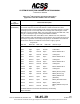
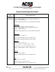
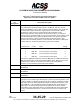
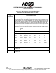
Table Of Contents
- T3CAS_Section_5
- 5 Adjustment/Test
- 1. General
- 2. Equipment
- 3. Initial Harness Checkout (New Installations Only)
- 4. System Self-Tests
- 5. Return-to-Service Test
- 6. Operational Software Loading Using an ARINC 615A Portable Data Loader or Compact Flash Card
- 7. Downloading Information from the TP3PCAS Using a CF Card
- 1. Obtain a New or Blank Compact Flash (CF) card.
- 2. Copy to the New or Blank CF card the appropriate ‘Header File’
- a) Header files are files copied to the New or Blank CF card that will instruct the computer unit what is desired to be downloaded.
- b) Header files needed to download Maintenance Data, Event Data and CRC Part Numbers can be obtained from ACSS Customer Services at +1-623-445-7070 or crc.acss@l-3com.com.
- 3. For downloading Maintenance Data, Event Data or CRC Part Numbers the aircraft does not need to be in an on-ground configuration.
- 4. Apply power to the computer unit.
- 5. Insert the CF card.
- 6. For ACSS part numbers 9005000-10000, -10101, -10202, and -10204 the DATA STATUS LED will UblinkU green once; this indicates the unit recognized that a CF card was inserted.
- 7. For ACSS part numbers 9005000-11203, -11801 and -55801 the DATA STATUS LED will UblinkU green while reading the header file and performing the action defined in the header file.
- 8. Flight Data Recording
- 1. T3CAS part numbers 9005000-10000, -10101, -10202, and -10204 only support FAT16 CF card formatting. T3CAS part numbers 9005000-11203, -11801 and -55801 support both FAT16 and FAT32 CF card formatting.
- B. Flight Data
- 1. Obtain a New or Blank CF Card.
- 2. Copy to the New or Blank CF Card the Appropriate Header File.
- 3. Header files are files copied to the New or Blank CF card that will instruct the computer unit what is desired to be downloaded.
- 4. For Flight Data Recording, the aircraft does not need to be in an on-ground configuration.
- 5. Apply power to the computer unit.
- 6. Insert the CF card.
- B. Flight Data
- 9. Downloaded Maintenance Data, Event Data And Flight Data May Be Sent To ACSS Customer Services For Analysis
- 5 Adjustment/Test
- T3CAS_Section_6
- T3CAS_Section_7
- 7 Maintenance Practices
- 1. General
- 2. Equipment and Materials
- 3. Procedure for the TP3PCAS Computer Unit
- 4. Procedure for the APM (Not applicable for part numbers 9005000-10000, -10101, -10202, -10204, or -11203)
- 5. Procedure for the Directional Antenna
- 6. Procedure for the Omnidirectional Antenna (Applicable to part numbers 9005000-11203, -11801 and -55801)
- 7. Procedure for the Control Panel
- 8. Procedure for the VSI/TRA Display
- 9. Instructions for Continued Airworthiness, FAR Part 25.1529
- 7 Maintenance Practices
- T3CAS_Section_8
- T3CAS_Section_9
- T3CAS_Section_10
- T3CAS_Appendix_A

SYSTEM DESCRIPTION AND INSTALLATION MANUAL
T
3
CAS/Part No.9005000
Table 4-2: T
3
CAS Computer Unit Interface Description
(Applicable to Part No. 9005000-11801 and -55801)
Connector
Pin
Designation
Functional Description
RMP-12B
(Continued)
NR-AS-10A Alternate
0.0 to 1.2 V dc: H = 2105.7V
Where H = Radio Altitude in ft and V = Voltage in V dc.
NR-AS-10A Curve Fit
0.0 to 18.1 V dc: H = 0.0833V
4
- 1.8887V
3
+ 15.5169V
2
- 21.9374V + 14.8097
Where H = Radio Altitude in ft and V = Voltage in V dc.
Each of the military radio altimeter types provide two outputs that are connected to
the T
3
CAS computer unit input pins. The two altimeter outputs are the Analog Data
Output and Analog Data Reliability Signal. The Data Reliability Signal is connected
to RMP-2K for source No.1 and RBP-3C for source No.2, except for altimeter type
LPIA. For radio altimeter type LPIA, the Analog Data Output must be connected to
RMP-2H (HI) and RMP-2J (LO), the Analog Data Reliability Signal must be
connected to RBP-3A (HI) and RBP-3B (LO), and the inputs RMP-2K and RBP-C3
are set high (greater than 18.5 V).
The metric radio altimeters are defined as follows:
Metric Altimeter Definition
No.1 Metric unit- 1000-m range, 25 mV/m scaling
No.2 Metric unit- 1000-m range, 20 mV/m scaling
No.3 Metric unit- 1500-m range, 20 mV/m scaling
No.4 Metric unit- 750-m range, 50 mV/m scaling
RMP-12C
RA/TA Block Transfer Program Input (NO)
This program input determines the type of block transfer that is made from the
T
3
CAS computer unit to the TA/RA displays. If this pin is grounded, the T
3
CAS
computer unit transmits in Honeywell BCA EFIS format. If the T
3
CAS computer unit
senses an open at this pin, it transmits in ARINC 735 format.
RMP-12D
Analog Radio Altimeter Type Select Program Input No.3 (NO)
See RMP-12B.
RMP-12E
Analog Radio Altimeter Type Select Program Input No.2 (NO)
See RMP-12B.
RMP-12F
Analog Radio Altimeter Type Select Program Input No.1 (NO)
See RMP-12B.
Pub. No. 8600200-001, Revision 004
34-45-29
4-55
04 Nov 2014
Use or disclosure of information on this page is subject to the restrictions in the proprietary notice of this document.